


5) Disconnect the battery cables.
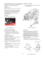
FIG.2-16
6) Disconnect the panel instrument set removing
bolts(4 nos.)
Note:
- Disconnect the linear shift control cable
- Disconnect the cable from both the steering lever side
and transmission.
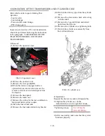
9) Remove the mounting bolts and dismounting the
FIG.2-18
8) Disconnect the hydraulic hose from the power
steering (orbitrol)
FIG.2-17
Note:
-Lift up the panel set and disconnect
the wiring couplers.
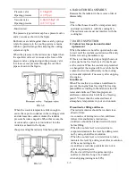
7) Remove the cover.
9) Remove the mounting bolts and dismounting the
dash panel
FIG.2-19 hardware Disassembly
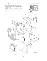
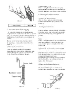
10) Disconnect the rubber hose from the suction
pipe.
2-9
Summary of Contents for T233 HST
Page 14: ...1 11...
Page 15: ...1 12...
Page 22: ...SECTION 3 GEAR TRAIN DIAGRAMS FIG 1 3 GEAR TRAIN DIAGRAM 1 19...
Page 33: ...SECTION 2 OPERATION CHART FOR DISASSEMBLY AND REASSEMBLY BY MAJOR BLOCKS 2 4...
Page 60: ...3 HST main pump case 4 5...
Page 64: ...6 Hydrostatic system schematic 4 8...
Page 100: ...3 Rear transmission case 5 15 Fig 5 23...
Page 121: ...Power Train Diagram Fig 5 60 5 36...
Page 210: ...SECTION 6 WIRING DIAGRAM 10 12...


