


2-3.REASSEMBLY
Reassembly the parts in reverse order of
disassembly,following these instructions.
1)Each friction surface should be coated
with grease in advance.
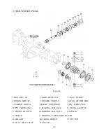
2)The bevel pinion and the ring gear make
a distinct pair after a mesh adjustment
performed at the factory. Consequently,
when reassembling the pair,be sure to
pair parts with a same reference number.
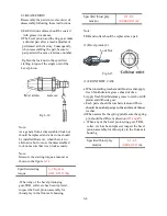
-Tighten the lock nut to the specified
starting torque of the single unit of the
bevel pinion.
Specified thrust play
mm(in)
0.1-0.3
(0.004-0.011 in)
Note:
TRB and collar should be replaced as a pair.
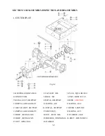
(1) Bevel pinion (8)
Lock Nut
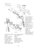
(2) FRONT DIFF CASE
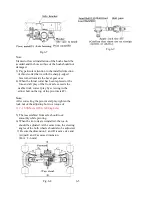
a.When installing washer and thrust washer,apply
fresh Molibdenium grease ahead of time.
b.Apply fresh Molibdenium grease to teeth of diff-
pinion and diff-side gear.
c.Each parts should be washed clean,and There
should be no sharp edge to the surface of thrust
Fig.6-15
Fig.6-14
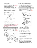
Note:
As a general rule,a disassembled lock nut
should be replaced and a new one should
be installed.However, when there is no
alternative but to reuse the disassembled
lock nut assure that it can lock securely.
Note:
Measure the starting torque a manner as
shown in the figure
6-14.
Specified starting
torque
6 -7 Kgf-cm
(0.43-0.51 ft.lbs
)
-When any of the bevel pinion,ring
gear,TRB, collar,etc.has been replaced,
inspect the bevel pinion assembly for
thrust play in the front axle housing.
should be no sharp edge to the surface of thrust
washer.
d.When assemble the spring pin,Be sure the spring
pin should be different direction
(Ø5 and Ø3)
e. When any of the bevel pinion,ring gear, TRB,
collar, etc. has been replaced, inspect the bevel
pinion assembly for thrust play in the front axle
housing.
Specified thrust play
mm(in)
0.1-0.3
(0.004-0.011
in)
6-8
Summary of Contents for T233 HST
Page 14: ...1 11...
Page 15: ...1 12...
Page 22: ...SECTION 3 GEAR TRAIN DIAGRAMS FIG 1 3 GEAR TRAIN DIAGRAM 1 19...
Page 33: ...SECTION 2 OPERATION CHART FOR DISASSEMBLY AND REASSEMBLY BY MAJOR BLOCKS 2 4...
Page 60: ...3 HST main pump case 4 5...
Page 64: ...6 Hydrostatic system schematic 4 8...
Page 100: ...3 Rear transmission case 5 15 Fig 5 23...
Page 121: ...Power Train Diagram Fig 5 60 5 36...
Page 210: ...SECTION 6 WIRING DIAGRAM 10 12...


