


2) During installation,be careful not to damage
the lips,and assure that it is pushed in
parallel to the shaft or hole.
3) When oil seals are installed,there should be
no turnover of the lips nor dislocation of the
springs.
4) When a multi-lip seal is installed, the
grooves between lips should be filed with
grease, not adhesive.
(3) O-rings
1) O-rings should be coated with grease before
installing.
2) Installed O-rings should have no slack or
twist.
3) Installed O-rings should maintain proper air
tightness.
(4) Snap rings
1) Snap ring installers should be designed so as
not to permanently deform the snap rings.
2) Installed snap rings should be seated
securely in the groove.
3) Be careful not to overload the snap ring to
(5) Spring(roll) pins
1) Spring pins should be driven in properly
as tightly.
2) Spring pins should be installed so that their
seams should face the direction from which
the load is applied.
3) The roll pins installed in the transmission or
other parts where much force is applied
should be retained with the wire.
Fig.2-2
3) Be careful not to overload the snap ring to
the extent that it is permanently deformed.
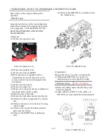
4) How to install the snap ring:
When installing a snap ring,install it as
shown in the figure with its round edge side
turned toward the part to be retained.This
round edge is formed when the snap ring is
pressed out.
Fig.2-1
(6) Cotter pins
When installed, cotter pins should be bent
securely at the ends as shown in the figure
Fig.2-3
(7) Bolts and nuts
1) Special bolts are installed at several
locations,so be sure not to interchange them
other bolts.
2) Bolts and nuts should be tightened to their
specified torque wrench.
3) When locking the bolts or nuts with wire or
a lock washer,
2-2
Summary of Contents for T233 HST
Page 14: ...1 11...
Page 15: ...1 12...
Page 22: ...SECTION 3 GEAR TRAIN DIAGRAMS FIG 1 3 GEAR TRAIN DIAGRAM 1 19...
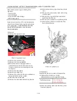
Page 33: ...SECTION 2 OPERATION CHART FOR DISASSEMBLY AND REASSEMBLY BY MAJOR BLOCKS 2 4...
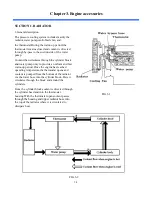
Page 60: ...3 HST main pump case 4 5...
Page 64: ...6 Hydrostatic system schematic 4 8...
Page 100: ...3 Rear transmission case 5 15 Fig 5 23...
Page 121: ...Power Train Diagram Fig 5 60 5 36...
Page 210: ...SECTION 6 WIRING DIAGRAM 10 12...


