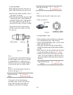


Fig.7-9
Apply force only to the shaded parts
Take care not to deform these portions
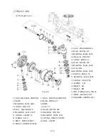
5) press the wheel shaft.
6) Install the wheel gear, the bearing, and snap ring on the wheel shaft and retain them.
7) Install the brake metal, the steel ball and the return spring
8) Install the friction plate, brake plate and the brake cover
Note : When installing the brake disc, Disc plate and separator should be arranged in correct order.
Apply an grease to the oil seal and take care not to be damaged when installing to the brake cam.
Pay particular attention to the installation of the snap ring
The assembled wheel pinion should rotate smoothly.
4) Replace the oil seal.
Install the bearing and the snap ring into the axle housing, and then press in the oil seal by applying
force only to the circumference as shown in the figure( Fig.7-9)
7-6
The assembled wheel pinion should rotate smoothly.
7) Apply adhesive (THREE BOND 1215) to the contact surfaces of the rear housing and rear transmission
case and then reassemble the rear housing by tightening the bolts to the specified torque.
Tightening torque
4.5-6.0 Kgf.m
Summary of Contents for T233 HST
Page 14: ...1 11...
Page 15: ...1 12...
Page 22: ...SECTION 3 GEAR TRAIN DIAGRAMS FIG 1 3 GEAR TRAIN DIAGRAM 1 19...
Page 33: ...SECTION 2 OPERATION CHART FOR DISASSEMBLY AND REASSEMBLY BY MAJOR BLOCKS 2 4...
Page 60: ...3 HST main pump case 4 5...
Page 64: ...6 Hydrostatic system schematic 4 8...
Page 100: ...3 Rear transmission case 5 15 Fig 5 23...
Page 121: ...Power Train Diagram Fig 5 60 5 36...
Page 210: ...SECTION 6 WIRING DIAGRAM 10 12...


