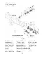


1.1 Disassembly
1) Release the bolt and nut and remove them.
2) Extract the snap ring(15) and the bearing(11) with a puller and
remove wheel gear(13)
3) Remove the brake metal tightening bolts and remove brake metal(5) with wheel pinion(7,2) and
disc brake assembly on it.
Note:
Removed oil seal(10) should be replaced
with a new one when reassembled
Fig.7-4
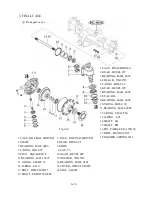
4) Remove the snap ring of wheel pinion(7, 2) (Fig.7-4) And individually separate the friction plates
④
,
⑤
7-4
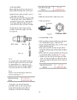
1.2. INSPECTION
1) Friction plates.
Replace the plates whose surfaces have been
become glossy by carbonization or whose
thickness exceeds the usable limit.
Standard thickness:mm(in)
3.4 (0.133)
Usable limit:mm (in)
3.1((0.122)
Fig.7-5
Note:
Also replace those whose grooves have been worn out completely even if only on one side
4) Remove the snap ring of wheel pinion(7, 2) (Fig.7-4) And individually separate the friction plates
④
,
brake cover(5), and separator plates
⑤
from each other.
5) The cam brake can be disassembled by removing Nut.
Note:
Be careful to keep the friction surfaces of the linings, brake metals free from damage and foreign matter.
Summary of Contents for T233 HST
Page 14: ...1 11...
Page 15: ...1 12...
Page 22: ...SECTION 3 GEAR TRAIN DIAGRAMS FIG 1 3 GEAR TRAIN DIAGRAM 1 19...
Page 33: ...SECTION 2 OPERATION CHART FOR DISASSEMBLY AND REASSEMBLY BY MAJOR BLOCKS 2 4...
Page 60: ...3 HST main pump case 4 5...
Page 64: ...6 Hydrostatic system schematic 4 8...
Page 100: ...3 Rear transmission case 5 15 Fig 5 23...
Page 121: ...Power Train Diagram Fig 5 60 5 36...
Page 210: ...SECTION 6 WIRING DIAGRAM 10 12...


