SECTION 4. TROUBLE SHOOTING
PROBLEMS AND PROBABLE CAUSES
COUNTERMEASURES
●
Steering wheel hard to turn
1)Too low tire inflation
2)Broken thrust bearing
3)Stuck or broken ball joint of tire-rod end
4)Seizure or poor lubrication of axle end bush
Inflate to specified value
Replace
Grease or replace
Grease or replace
●
Vibrating or pulling steering wheel
1)Unbalanced wheels
2)Wheel deflation
3)Unequal diameter of both tires
4)Loose,worn,or damaged wheel axle bearing
5)Loose,worn,or damaged wheel steering wheel shaft
6)Worn final case bush
7)Loose final case-front axle tightening bolt
8)Loose front wheel(tire)tightening nuts1)
Adjust balance
Repair or replace
Adjust inflation or replace
Repair or replace
Retighten or replace
Replace
Retighten
Retighten
●
Steering wheel tends to turn to the right or left while traveling on straight paved road.
1) Deflected wear of tire
Replace
1) Deflected wear of tire
2)Different tire diameters
3)Damaged final case bearing
Replace
Adjust inflation or replace
Replace
●
Excessive or eccentric wear of tire
1)Improper tire inflation
2)Worn front wheel shaft bearing
3)Poorly adjusted toe-in
4)Front wheel drive is always engaged
Adjust
Replace
Readjust
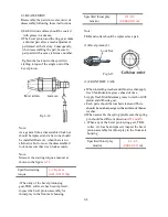
correctly:2-6mm
(0.08-0.24 in)
Engage FWD only when required
●
Noise
1)Loose fasteners
2)Worn or damaged final case bearing
3)Worn bush
4)Wear or poor movement of tie-rod end
5)Excessive backlash of differential and bevel gear
Tighten correctly to specified torque
Replace
Replace
Lubricate or replace
Adjust
●
Different steering angles in both directions
1)Lengths of RH and LH tie-rods are different
Adjust
6-15
Summary of Contents for T233 HST
Page 14: ...1 11...
Page 15: ...1 12...
Page 22: ...SECTION 3 GEAR TRAIN DIAGRAMS FIG 1 3 GEAR TRAIN DIAGRAM 1 19...
Page 33: ...SECTION 2 OPERATION CHART FOR DISASSEMBLY AND REASSEMBLY BY MAJOR BLOCKS 2 4...
Page 60: ...3 HST main pump case 4 5...
Page 64: ...6 Hydrostatic system schematic 4 8...
Page 100: ...3 Rear transmission case 5 15 Fig 5 23...
Page 121: ...Power Train Diagram Fig 5 60 5 36...
Page 210: ...SECTION 6 WIRING DIAGRAM 10 12...


