


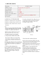

SECTION 3. SEPARATION OF MAJOR COMPONENTS
1.SEPARATION OF THE FRONT
AXLE AND AXLE BRACKET
Parts which can be inspected during This
operation
-Center pivot
-Final case
-Differential gear
(1) Removal
1) Hold the front hitch or the front bracket
securely with a crane or stands.
2) Support the front axle with a jack
3) Remove both right-hand and left-hand
steering hose.
4) Remove the pivot metal bolts.
5) Remove the front axle assembly forward.
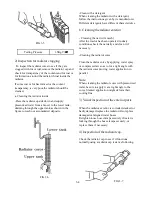
Note:
When working on the 4WD version,the
drive shaft should be removed ahead of
time.
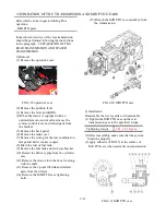
(2) Installation
1) Install the front axle assembly.
FIG.2-3 Drive shaft
FIG.2-2 Front axle
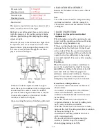
2) Install both pivot metals(supports)
Note:
Apply grease to the bushing and fill the oil seal
with grease ahead of time. Install the oil seal
carefully not to allow its lips to turn over.
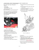
3) install both of the right and left steering hose.
FIG.2-4 pivot metals(supports)
Apply grease to the bushing
FIG.2-1 steering hose and tie rods
2-5
Summary of Contents for T233 HST
Page 14: ...1 11...
Page 15: ...1 12...
Page 22: ...SECTION 3 GEAR TRAIN DIAGRAMS FIG 1 3 GEAR TRAIN DIAGRAM 1 19...
Page 33: ...SECTION 2 OPERATION CHART FOR DISASSEMBLY AND REASSEMBLY BY MAJOR BLOCKS 2 4...
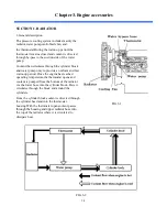
Page 60: ...3 HST main pump case 4 5...
Page 64: ...6 Hydrostatic system schematic 4 8...
Page 100: ...3 Rear transmission case 5 15 Fig 5 23...
Page 121: ...Power Train Diagram Fig 5 60 5 36...
Page 210: ...SECTION 6 WIRING DIAGRAM 10 12...


