


2.1 DISASSEMBLY
Oil seal
Snap ring
Snap ring
Diff case
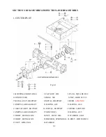
1) As concerns operation prior to removal of
the front axle,refer to the paragraph covering
disassembly of the center pivot
2) Remove both wheels
3) Remove the drain plug from the final case and
drain oil from the final case.
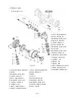
4) remove both final case assembly (A and B)
from the front axle( Fig.6-11)
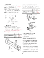
6) Remove the bearings from the Axle housing
And the ring gear, and then the ring gear can
be separated from the Axle housing.
7) Remove the straight pin(4) which retains the
axle housing.
Note: Discard the removed straight pin and oil
seal and install a new pin and Oil seal
when reassembled,because this pin and oil
seal is apt to be damaged when removed.
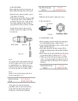
8) Remove the snap ring and the bevel pinion
can then be removed together with the
TRB’s (Fig.6-11)
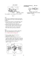
9) When separating the TRB’s from the bevel
pinion,release the calking of the lock nut and
remove the bearings.
Lock Nut
Oil seal
Bevel pinion
Fig.6-11
5) Remove the oil seal, assuring parallelism of
the ring gear and bearing
Note:
The number of shims(1) installed and the the
shimming thickness should be noted for later
reference.
Fig.6-12
Fig.6-13
Note:
The lock nut should be calked at a point
completely apart from the threads may damage
the threads of the bevel pinion.
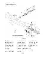
2.2 INSPECTION
1) visually check the bearing surfaces of the
bevel pinion and ring gear teeth.
Note:
The bevel pinion and the ring gear should be
replaced as a pair.
2) seriously worn or damaged parts should be
replaced.
6-7
Summary of Contents for T233 HST
Page 14: ...1 11...
Page 15: ...1 12...
Page 22: ...SECTION 3 GEAR TRAIN DIAGRAMS FIG 1 3 GEAR TRAIN DIAGRAM 1 19...
Page 33: ...SECTION 2 OPERATION CHART FOR DISASSEMBLY AND REASSEMBLY BY MAJOR BLOCKS 2 4...
Page 60: ...3 HST main pump case 4 5...
Page 64: ...6 Hydrostatic system schematic 4 8...
Page 100: ...3 Rear transmission case 5 15 Fig 5 23...
Page 121: ...Power Train Diagram Fig 5 60 5 36...
Page 210: ...SECTION 6 WIRING DIAGRAM 10 12...


