18
4. Operation
4.4.11 Operation in Fault Mode
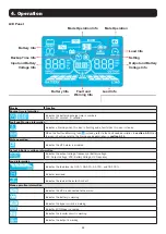
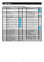
1) When the Fault LED illuminates and the alarm sounds continuously, there is a fatal error in the UPS. Users can view the fault code from
the LCD panel. Refer to the table in
section 6. Troubleshooting
for more information.
2) Check the loads, wiring, ventilation, utility, battery, etc. after a fault occurs. Do not attempt to turn on the UPS again until the problem
is resolved. If the problem cannot be fixed, please contact Tripp Lite Tech Support.
3) In the event of an emergency, immediately cut off the utility connection, external battery, and output to avoid further risk or danger.
4.4.12 Operation in Maintenance Mode (for Models with a Maintenance Bypass Switch Only)
1) This operation should only be performed by maintenance personnel or qualified technicians. When the UPS needs to be repaired or
serviced and the load cannot be shut off, the UPS should be put into Maintenance Mode.
2) First, switch off the UPS.
3) Remove the cover of the maintenance bypass switch.
4) Turn the maintenance switch to “BPS” position.
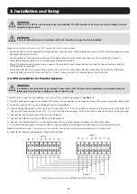
Warning: (for Parallel System Setups Only)
• Before turning on the parallel system to activate the inverter, make sure all UPS maintenance switches are set to the
same position.
• When the parallel system is turned on to work through the inverter, do not operate the maintenance switch of any
unit.
4.5 Parallel UPS Operation
4.5.1 Parallel System Initial Startup
Before initial startup, ensure all UPS systems have the same configuration and can be connected in parallel.
1) Turn on each UPS to On-line Mode (refer to
section 4.4.1
). Using a multimeter, measure the inverter output voltage of each phase for
each UPS to confirm that the inverter voltage difference between actual output and setting value is less than 1.5V (typically 1V). If the
difference is greater than 1.5V, calibrate the voltage by configuring the inverter voltage adjustment (refer to Program Codes 15, 16 and
17, in
section 4.7
) in the LCD setting. If the voltage difference after calibration remains greater than 1.5V, contact Tripp Lite Technical
Support for further assistance.
2) Calibrate the output voltage measurement by configuring the output voltage calibration (refer to Program Codes 18, 19, and 20, in
section 4.7
) in the LCD panel to ensure the difference between the real output voltage and the detected value of the UPS is less than
1V.
3) Turn off each UPS (refer to
section 4.4.7
), then follow the wiring procedure in
section 3.4
.
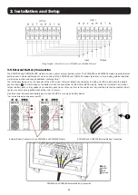
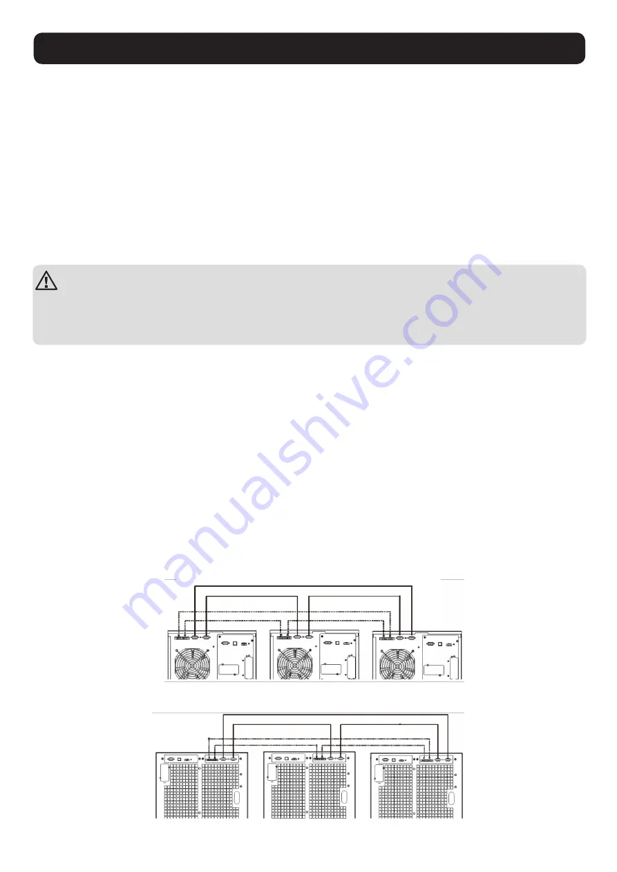
4) Remove the metal cover to access the parallel communication ports on the UPS. Connect each UPS one at a time (maximum of three
units for parallel installation) with the parallel cable and shared current cable. Follow the parallel communication cable configuration in
the figure below, then reinstall the metal cover.
S3M30KX/S3M40KX Parallel System UPS Wiring
Current Sharing Cable
Current Sharing Cable
Parallel Cable
Parallel Cable
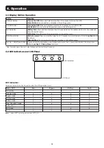
S3M60KX/S3M80KX Parallel System UPS Wiring
Summary of Contents for S3M30KX
Page 125: ...125 2 4 2 5 2 6 2 7 TN 4 2 EN IEC 62040 1...
Page 129: ...129 3 3 2 1 1 3 1 2 3 2 3 5 3 1 3 2...
Page 132: ...132 3 OFF R S T N 3 4 3 7 1 2 3 5 3 R S T N R S T N 4 5 6 7 8 S3M30KX S3M40KX 2 1...
Page 135: ...135 4 H M S Fault Warning 4 9 4 11 VAC VDC Hz 0 25 26 50 51 75 76 100 ECO...
Page 147: ...147 4 2...
Page 148: ...148 ECO ECO 4...
Page 149: ...149 4 CVCF CF 50 60 4...
Page 150: ...150 2 CVCF Test 0 5 I P 4...
Page 151: ...151 4 3 4 11 4 9...
Page 155: ...155 6 EPO EPO OFF EPO 43 14 15 16 17 18 19 7 02 4 7 3 CHE Enter CHE Enter L2 L3 L2 L3...
Page 156: ...156 7 7 1 40 C 90 6 24 24 3 7 2 BUS 7 3 Tripp Lite S3MX 1 0 40 C 2 25 C 3 24 7 4 Tripp Lite...

