background image

Manual x/e-touchPANEL 02 | 01-2021 | 2.9 | en

Interfaces

c

107 / 118

How to

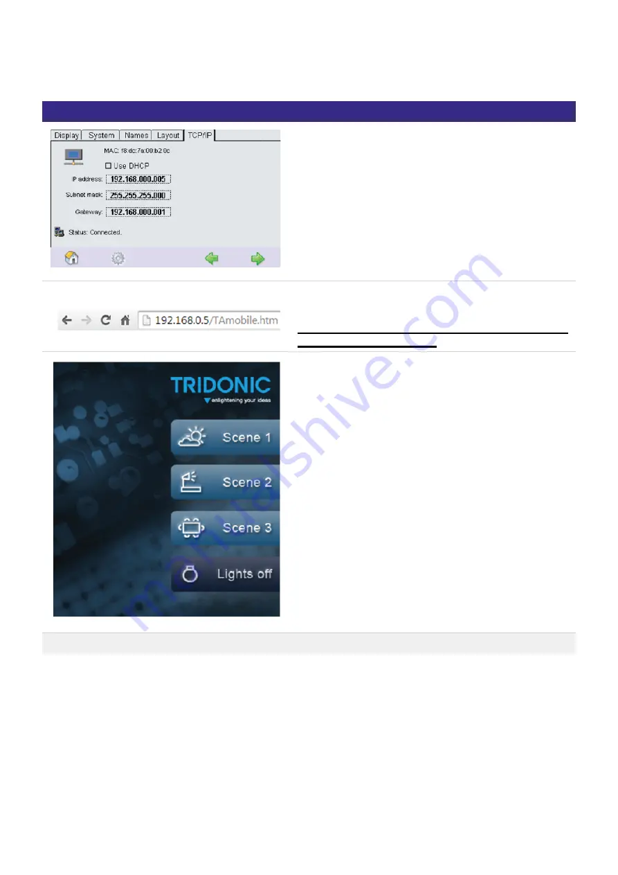
Connect your x/e-touchPANEL to Ethernet.


Type the IP address followed by /TAmobile.htm in your
Web Browser

! Attention The xetouch software is case sensitive. Pay
attention to correct spelling.

You will see the TA_mobile Webpage.

On this Page you can recall Scene 1-3 and Switch the
lights off.

How to Editing the page example Google Chrome

Summary of Contents for x/e-touchPANEL 02

Page 1: ...Sensors Controls x e touchPANEL02 Manual ...

Page 2: ... 2 Settings for Emergency Application 20 5 3 DALI communication test 22 5 4 Addressing and grouping emergency units 23 5 5 Programming the prolong time 27 5 6 Configuring the error signalling 28 5 7 Identifying emergency units 31 5 8 Manually testing emergency units 32 5 9 Determining the starting time for automated testing 35 5 10 Set up eMail function 38 5 11 Deactivating emergency units 39 6 Ba...

Page 3: ... 7 3 USB interface 89 7 4 Ethernet interface 99 7 5 Uploading downloading files and test protocols 103 8 Appendix 113 8 1 Technical data 113 8 2 Circuit diagrams 114 8 3 Schedule for Ethernet connections 115 8 4 Help in the case of problems 117 8 5 Reference list 118 ...

Page 4: ...95 0 F 43 5572 20176 www tridonic com The instructions in this section have been compiled to ensure that operators and users of DALI control system x e touchPANEL 02 from Tridonic are able to detect potential risks in good time and take the necessary preventative measures I NOTICE Software updates The software for the x e touchPANEL 02 is continuously developed and improved Software updates are pr...

Page 5: ...e following operating devices may be connected 2 2 Dangers associated with the operation of the system The following safety instructions must additionally be observed when using the x e touchPANEL for controlling emergency lighting systems The operator must ensure that all users fully understand these instructions and adhere to them _ EM PRO _ EM powerLED PRO _ Operating devices with a DALI interf...

Page 6: ...r of the comfortDIM series is possible 3 2 1 Used navigational symbols For navigation within the software different symbols are used Which symbols are displayed depends on the selected settings The most important symbols are explained below Symbol Naming Home menu Main menu Time Date menu Previous page and next page via the integrated touchpanel _ via a PC which must be connected to the x e touchP...

Page 7: ... several DALI lines can be connected via controllers DALI provides the system programmer with a set of commands that facilitates targeted programming without any special knowledge of lighting technology DALI also offers the following additional advantages compared with analog technology Emergency Application _ Basic Colour Plug Application _ Control line polarity does not need to be observed _ Use...

Page 8: ...or deactivate the screen saver Locking the display Locking of releasing the touchscreen password protected System Program version Displays the x touch software version Device name Enter the name for the x e touchPANEL For identification when several devices are used Reset to factory defaults Reset the settings to the factory defaults e g Layout Net recovery action Control the behaviour after the p...

Page 9: ... the Ethernet connection Gateway Entering the gateway for the Ethernet connection Status Displays the connection status I NOTICE In addition to the tabs mentioned here there are three more But these are not available in all Applications Name and Layout are available only in Basic Colour Plug Application _ Emergency is only available in Emergency application _ These three tabs basic settings are di...

Page 10: ...k on the arrow key next to the Language entry The list of languages is displayed Click on the desired language The software interface is displayed in the selected language 4 2 2 Selecting the application To call up another Application to the one currently being used Click on the Main menu symbol The Main menu is displayed Click on the Configuration button The Configuration page is displayed Select...

Page 11: ...est with OK A restart of the x e touchPANEL is performed depending on the Application 4 2 3 DALI Routing Click on the Main menu symbol The Main menu is displayed Click on the Configuration button The Configuration page is displayed Select the System tab The System tab is displayed Allows to send commands from other controls e g DALI XC TOUCHPANEL 02 from DALI line A to line B and vice versa This F...

Page 12: ...located Confirm the settings with OK 4 2 5 Cleaning the touchscreen The touchscreen can be temporarily disabled for cleaning to avoid accidentally changing settings The cleaning is was di also possible without a password in case the configuration sabled Click on the Main menu symbol The Main menu is displayed Click on the Configuration button The Configuration page is displayed The Display tab is ...

Page 13: ...rotection Access can be limited to two levels by assigning a password Locking the configuration Click on the Main menu symbol The Main menu is displayed Click on the Configuration button The Configuration page is displayed The Display tab is displayed Activate the Lock configuration check box The password protection is set factory default 1234 A dialog box is displayed to change the password I NOT...

Page 14: ...rotection is set factory default 5678 A dialog box is displayed to change the password In order to change the password click on Yes and enter the old password in the following dialog box Enter the new password in the following two boxes and confirm with OK in each case Click on No if the password is not being changed The touchpanel can only be operated once the password is entered after the screen...

Page 15: ... and schedule list are continued Click on the Main menu symbol The Main menu is displayed Click on the Configuration button The Configuration page is displayed Click on the System tab The System tab is displayed Click on the Action at net recovery button The dialog box Net recovery action is displayed Activate the check box and confirm with OK ...

Page 16: ... device name and program version are displayed Click on the device name to change the device name The dialog box Keyboard is displayed Enter the new name and confirm with the Enter key Click on the Esc key to cancel the process 4 2 10 Rename Groups Scenes Sequences Schedules It is possible to rename groups scenes sequences and schedules directly on your Computer Find more information in Interfaces...

Page 17: ...r verification The x e touchPANEL with a colour touchscreen provides the following functions for operating the emergency units A frame light is integrated in the x e touchPANEL It supports the status line of the system 5 1 2 Main pages The menu of the x e touchPANEL consists of three main pages These pages are opened by clicking on the following symbols Symbol Page System status Test protocol Main...

Page 18: ...ors in the system The number of installed emergency units is also indicated Error is displayed on the System status page if there is an error in the system The number of errors is also indicated 5 1 4 Test protocol The function and duration tests performed including their dates and results are recorded for every emergency unit on the Test protocol page ...

Page 19: ...n menu Button Function Test times Used to specify a time schedule for the function and duration test Commissioning test Used to start the function and duration test manually Identification tool Used to convert the identification flashing into the emergency unit address I NOTICE TestBook entries are written to the buffer memory If the memory is full the oldest will be deleted Test Book to make room...

Page 20: ...s of the specific emergency lighting functions 5 2 Settings for Emergency Application 5 2 1 Adjusting the frame light The x e touchPANEL has an additional frame light that supports the system s status line Click on the Main menu symbol The Main menu is displayed Click on the Configuration button The Configuration page is displayed The Display tab is displayed Click on the Framelight button The dia...

Page 21: ...is indicated in the test protocol Click on the Main menu symbol The Main menu is displayed Click on the Configuration button The Configuration page is displayed Click on the Names tab The Names tab is displayed Click on the Emergency units dropdown menu and select the emergency unit Click on the Edit button to enter a name for the emergency unit A keyboard is displayed Enter a unit name and confir...

Page 22: ...nd Recall max and Recall min are transmitted alternately seconds apart Click on the Main menu symbol The Main menu is displayed Click on the Addressing grouping button The dialog box Addressing method is displayed Select the DALI A or DALI B line in the DALI Communication test menu item Click on the Next button The test is performed Repeat step 3 for the other DALI line if necessary ...

Page 23: ...completed is displayed click on the Complete button The Grouping page is displayed Each emergency unit is displayed as part of a group System extension If new emergency units have been added to an existing system an address is assigned to these units The addresses of the existing DALI devices remain unchanged _ Reinitialization A new address is assigned to all DALI devices in the system _ No devic...

Page 24: ...y units of a room the grouping can be changed Click on the Main menu button Click on the Addressing grouping button Select the addressing method Grouping only no search for devices The addresses of existing DALI devices remain unchanged Click on the Next button When the message Search completed is displayed click on the Complete button The Grouping page is displayed Each emergency unit is displaye...

Page 25: ...eld The emergency unit is displayed in the group Repeat steps 1 to 3 for other emergency units if necessary After the automatic addressing the addresses DALI A0 to A63 and DALI B64 to B127 and specific operating devices if necessary are displayed e g HID The following operating elements are available for grouping Element Meaning Function Use the arrow keys to select the operating device that is to...

Page 26: ... groups _ Devices can be assigned to multiple groups _ Several groups can be assigned to a scene _ If now a scene is called and that scene is assigned to several groups And several of these groups include the same device there may be a conflict because it is not clear which of the values the device saves In this case the rule above applies Example 1 Device 1 is in G1 and G2 _ Both groups are assig...

Page 27: ...of short mains voltage interruptions The basic setting of the emergency units is 0 minutes Click on the Main menu symbol The Main menu is displayed Click on the Configuration button The Configuration page is displayed Click on the Emergency tab The Emergency tab is displayed Click on the Prolong time dropdown menu and select the desired time Click on the Program prolong time button I NOTICE The pr...

Page 28: ...n menu symbol The Main menu is displayed Click on the Addressing grouping button Select addressing method System extension Reinitialization or Grouping only no search for devices With System extension the addresses of existing DALI devices remain unchanged With Reinitialization a new address is assigned to all DALI devices in the system Click on the Next button When the message Search completed is...

Page 29: ...cy Application c 29 118 6 7 8 Use the arrow keys to select both addresses for the Status report OK and Status report Error Click on the green arrow key at the bottom right and select the Save symbol The two addresses for error signalling are stored ...

Page 30: ...e Configuration button The Configuration page is displayed Click on the Emergency tab The Emergency tab is displayed Activate the check box Send failure status to DALI A Error signalling is activated The following messages are displayed at the error signalling addresses Status report Meaning OK No error is present on both DALI lines Error An error is present on one of the two DALI lines ...

Page 31: ...ED identification signal into a DALI address Using the integrated identification tool on the x e touchPANEL you can determine the address of an emergency unit as described below Click on the Main menu symbol The Main menu is displayed Click on the Identification DALI A or Identifikation DALI B button The LEDs of the emergency units flash green and red Click on the Identification Tool button The di...

Page 32: ... the bottom right of the touchpanel while the test is running The batteries have been charged for at least 24 hours Click on the Main menu symbol The Main menu is displayed Click on the Commissioning Test button The dialog box Start test is displayed Select the check box start function test or start duration test and confirm with OK The selected test is performed and displayed in the status line A...

Page 33: ...y unit Test Type of test FT function test DT duration test CT communication test and date of test Status Result of test OK Test successful Lamp defective Lamp Error Battery fault Battery Failure Error in the emergency unit Charger Failure Communication error Lamp error _ Lamp wrong _ Lamp wiring wrong _ Battery capacity too low _ Battery defective _ Battery wiring wrong _ Emergency unit defective ...

Page 34: ...e battery for at least 20 hours and start duration test manually _ Even if the function test is performed successfully the x e touchPANEL shows the error message T to signal that the error detected during the last duration test has not been corrected _ Replace battery and perform operation test manually _ I NOTICE If a fault has been eliminated this must be verified by performing a test on this em...

Page 35: ...med manually weekly The function test is performed every week every 2nd week The function test is performed in the first and third week of the month monthly The function test is performed in the first week of the month Duration test manual The duration test must be performed manually monthly The duration test is performed in the first week of the month quarterly The duration test is performed in t...

Page 36: ...lick on the extended button The dialog box Extended settings is displayed For each group set the day of the week and the time of day Click on the respective dropdown menu and select the day of the week or the time of day and set the desired time using the arrows I NOTICE The first week of a month is defined to last from the 1st to the 7th day of the month The third week of a month is defined to la...

Page 37: ...5 6 7 8 9 For the communication test click on the respective time The dialog box Entry time is displayed Set time Comfirm with click on OK Starting time for communication test is set If the feature cyclic communication test is used the test will be repeated every 4 seconds ...

Page 38: ...e two options if test OK or if test failed if if test failed was activated an additional option for communication test is available to address Enter the address to which the email should be sent from address Enter the address you want to set as sender SMTP server Enter appropriate server name Contact IT department if you don t know login Enter the login name for the sender e mail password Enter th...

Page 39: ...ick on the Main menu symbol The Main menu is displayed Click on the Configuration button The Configuration page is displayed Click on the Emergency tab The Emergency tab is displayed Click on the Rest button The emergency units are switched off When the main power supply is switched on again the emergency units are reactivated To activate the emergency units before switching on the main power supp...

Page 40: ...y tab The Emergency tab is displayed Click on the Inhibit button The LEDs of the emergency units emit a green double flash Switch off the main power supply within 15 minutes The emergency units do not switch on When the main power supply is switched on again the emergency units are reactivated In order to reactivate the emergency units without switching the main power supply on and off again click...

Page 41: ... lines 2 Connection Maximum 128 DALI operating devices Bus supply External Interfaces USB Ethernet Frame light yes Applications _ Basic for white light applications _ Colour for RGBW applications _ Plug for simple RGBW applications with preconfigured operating devices where the addressing is already set using coded connectors _ Configuration of _ 16 scenes _ 99 light sources _ 7 time controlled sc...

Page 42: ...Manual x e touchPANEL 02 01 2021 2 9 en Basic Colour Plug Application c 42 118 Display light Always ON or automatically dimmed 2 min after last activation ...

Page 43: ...very 24 hours at a preset time of the day Schedule list SDLL Each schedule is assigned to one weekday In this way a schedule list is created for the calendar controlled uninterruptible automation of lighting situations Scheduler When Scheduler is activated it appears in the Home menu and enables a sequence schedule list and schedule to be controlled manually Start Pause Stop and Off Basic Applicat...

Page 44: ...tically controlled by the software W R G B Z1 1 5 6 7 Z2 2 8 9 10 Z3 3 11 12 13 Z4 4 14 15 16 Typical application examples for the Colour Application are rooms where mainly RGBW operating devices are used to implement freely design colour changes and colour effects e g in shop windows bars and exhibition spaces You can define a maximum of Plug Application With the Plug Application only one zone is...

Page 45: ...ens the page where the function is started stopped Opens the following or previous page in a menu Home In the Home menu lighting situations can be called up manually see also Operation in the Home menu p 77 The number and selection of lighting situations are configured depending on the application The buttons of the lighting situations can be designed as desired e g with pictograms or specific nam...

Page 46: ...in menu basic software settings are configured lighting situations are defined and time sequences are specified The Main menu is different in the Basic and Colour Applications Application BASIC Application COLOR Button Function Colour Temperature Opens the page where you can configure the Colour Temperature Schedule list SDLL Opens the page where you can assign schedules to certain weekdays Schedu...

Page 47: ...ens the page where you can select the addressing method address the devices and split them into groups or zones Configuration Opens the page where you can configure the software and communicate via interfaces Click on the Main menu symbol The Main menu is displayed Click the button for the desired submenu ...

Page 48: ...s 4 zones or 8 colour scenes on each page in the Colour Application Scheduler Activate the Scheduler The Scheduler enables a sequence schedule list and schedule to be controlled manually Start Pause Stop and Off G1 G4 G5 G8 G9 G12 G13 G16 Colour Application G1 G4 Select buttons for the Home menu 4 groups on each page In the Colour Application it is only possible to have the 4 white groups Clean Se...

Page 49: ...irm with OK The frame light is displayed in the selected colour or goes out Click on the arrow key to set the display light The selection box is displayed Activate the Automatically dimmed entry to dim the display light 2 minutes after last activation or Activate the Always on entry to leave the display light constant 6 2 2 Assigning names You can assign application specific names to Scenes Sequen...

Page 50: ...ces Schedules p 110 USB Rename Groups Scenes Sequences Schedules p 97 6 2 3 Selecting a screen design for the Home menu Different screen designs can be selected for the Home menu The Display tab is open in the Configuration menu Click on the Main menu symbol The Main menu is displayed Click on the Configuration button The Configuration page is displayed The Display tab is displayed Click on an arr...

Page 51: ...ion c 51 118 3 4 Select the desired design If the Modern design as been selected the main menus will be shown as Menu 1 or Menu 2 for example For the Designs Classic and Classic Grey the background colour can be changed How to Go to and select main menu Configuration ...

Page 52: ...ation c 52 118 In the Display window you will see the new field Colour Select the field Colour In the new Field you can change the Design colours For Background inactive buttons and active buttons The colour can be changed in two ways By clicking in the colour field ...

Page 53: ...Manual x e touchPANEL 02 01 2021 2 9 en Basic Colour Plug Application c 53 118 Or by typing in the RGB values I NOTICE The following only shows illustrations for the Classic design ...

Page 54: ...mponents is only displayed if this is supported by the devices Device Type Abbreviation Type Example Tridonic DT 0 Fluorescent lamps PCA DT 1 EM Self contained emergency lighting EM PRO DT 2 HID Discharge lamps excluding fluorescent lamps PCI Outdoor DT 3 LV Low voltage halogen lamps TE o4a DT 4 INC Supply voltage controller for incandescent lamps PCD 300 o4a DT 5 CONF conversion from digital sign...

Page 55: ...he operating device that is to be assigned to a group Use the button to remove the selected device from the group System extension Only newly added operating devices are addressed The existing addresses remain unchanged _ Reinitiialization All operating devices in the system are re addressed The existing addresses are overwritten _ No device search only grouping Only existing devices are displayed...

Page 56: ...everal groups the value of the highest group number is saved For a more detailed explanation DALI has max 16 groups _ Devices can be assigned to multiple groups _ Several groups can be assigned to a scene _ If now a scene is called and that scene is assigned to several groups And several of these groups include the same device there may be a conflict because it is not clear which of the values the...

Page 57: ...evel With x e touch panel you are able to use color temperature Not supported Colour types are xy coordinate primary N RGBWAF DALI communication test The consistency of the DALI connection can be tested if necessary The command Recall max and Recall min are transmitted alternately seconds apart Click on the Main menu symbol The Main menu is displayed Click on the Addressing grouping button The dia...

Page 58: ...symbol over the touchscreen to the group field The corresponding operating device reacts when the device address is touched I NOTICE Tridonic recommends saving Somfy operating devices in separate groups i e separately from other operating devices I NOTICE When the Addressing grouping button is clicked for the first time a page will open with information about registering the x e touchPANEL softwar...

Page 59: ... keys to select the group and confirm with OK The group is displayed Use the arrow keys to select the address of the operating device Move the operating device 1 into the group field using Drag Drop The device address is displayed in the group field of the currently selected group Use the arrow keys to select other addresses and drag them into the same group field Click on the Save button The dial...

Page 60: ...min and max Light Level to 101 then no Light Level will be sent CAUTION If the parameter Light Level MIN is set to 0 it will be displayed in the GUI as 1 Still the parameter will work as expected The light will be turned off in the time between 18 00 and 6 00 If the parameter Light Level MIN is set to 1 it will be displayed correctly as 1 and the light will stay at 1 dimming level in the time betw...

Page 61: ...g situation is created A maximum of 16 scenes each with a maximum of 16 groups can be saved in each scene The following operating elements are available to set a scene Element Meaning Function The scene number S1 is preset at the factory the scene name Scene 1 can be assigned as desired A scroll bar visualises the setting of the dimming value Change the dimming value using the arrow keys or the bl...

Page 62: ...utton to open the dialog box Save scene The group settings are saved in the desired scene Use the green arrow key to switch to the next page Configuring scenes One of the following settings are selected for each group in a scene One or several groups are defined Click on the Main menu symbol The Main menu is displayed Click on the Scenes S button The page S is displayed Click on the Folder button ...

Page 63: ...o pages Click on the Folder button to define further scenes and use the arrow keys to select a new scene Repeat steps 2 to 7 if necessary 6 3 3 Sequence Start duration and repetition of scenes are saved in a defined order in a sequence You can assign scenes to a sequence several times and in any order A sequence is ended if The following operating elements are available to define a sequence I NOTI...

Page 64: ...en the dialog box Load sequence Click on the Save button to open the dialog box Save sequence The current settings are saved in the desired sequence Click on the Timeline button to set the duration and number of repetitions of a sequence Configuring sequences In a sequence scenes are saved at a defined position on a timeline The number of repetitions is determined with the digits 2 to 6 and Loop I...

Page 65: ...n the number field Select the duration in the dialog box Time entry and confirm with OK Click on the arrow keys in the Loop field until the number of repetitions is set Confirm the entries with OK With the arrow keys and the magnifier adjust the timeline section in such a way that the starting time for the scene is visible Use the arrow keys to select the marker Scene S1 S16 Move the marker Scene ...

Page 66: ...ired fade time 0 to 90 sec is displayed Confirm the settings with OK Click on the Save button The dialog box Save sequence is displayed If necessary change the sequence in which the scenes are to be saved and confirm with OK The sequence is saved Repeat steps 1 to 7 to set the exact starting or fade time of scenes for further sequences 6 3 4 Schedule SDL A schedule comprises the time between 0 00 ...

Page 67: ...e set several times Use this button to remove the selected scene or sequence from the schedule The timeline visualises Use the arrow keys to move the visible section of the timeline Use the magnifier to enlarge or reduce the timeline section The Folder button opens up the dialog box Select schedule The Save button opens the dialog box Save schedule The current settings are saved in the desired sch...

Page 68: ...ule and confirm with OK The schedule is displayed Use the arrow keys to select the marker Scene or Sequence Move the marker Scene or Sequence to the desired position on the timeline using Drag Drop Repeat steps 4 to 5 to enter further scenes or sequences Click on the Save button The dialog box Save is displayed If necessary change the schedule in which the scenes sequences are to be saved and conf...

Page 69: ...line Change and save the schedule as required 6 3 5 Configuring a schedule list Assign the schedules that you have defined to the days of the week to create a continuous uninterrupted schedule list The first schedule is assigned to all weekdays in the factory setting One or several schedules are defined The Main menu is visible Click on the Main menu symbol The Main menu is displayed Click on the ...

Page 70: ...118 4 5 Select the schedule or Select Off Repeat steps 2 to 5 for each weekday The schedule list is saved without confirmation I NOTICE A schedule list is started ended or interrupted in the Home menu see Manually switching a sequence schedule or schedule list p 83 ...

Page 71: ...GB RGBW operating device is assigned to the colour scale red green blue white of a zone using Drag Drop Four zones with 4 colour scales are available Each colour scale of a zone corresponds to a group Since the three groups Red Green and Blue are necessary for colour mixing and only the group White is not required only the groups White max 4 groups can be controlled individually For basic lighting...

Page 72: ...on Each operating device is addressed The page Addressing of Z is displayed Click on the Folder button to select the zone in which the operating devices are to be saved The dialog box Select zone is displayed Use the arrow keys to select the zone and confirm with OK The zone is displayed Use the arrow keys to select the address of the operating device to be assigned to the zone Move the address of...

Page 73: ...n The SQ page is displayed Click on the Folder button to select the colour sequence in which the colour events are to be saved The dialog box Load sequence is displayed Use the arrow keys to select the colour sequence and confirm with OK The sequence is displayed Click on the Timeline button to enter the Duration of the colour sequence The dialog box Timeline is displayed Click on the arrow keys o...

Page 74: ...change the colour sequence in which the colour events are to be saved and confirm with OK The colour sequence is saved with the current settings Repeat steps 2 to 12 to define further colour sequences 6 4 4 Configuring colour events This chapter explains how to configure the exact starting time fade time and colour of the colour event You can select the colour in a colour table or enter the indivi...

Page 75: ...nter the RGBW value numerically enter the RGBW values in the third tab Activate the Zone check box Z1 to Z4 to assign the colour event to one or several zones To define the exact duration and fade time click on the Timing Fading button Use the arrow keys to select the values and confirm with OK Confirm the entries with OK Repeat steps 2 to 6 to define further colour events Confirm the settings wit...

Page 76: ...started 6 5 2 Addressing Addressing is done on a connector on the operating device Addressing is therefore not possible and necessary 6 5 3 Zone assignment There is only 1 zone with 4 colour scales in the Plug Application Each colour scale corresponds to a group Depending on the configuration the groups can be switched and dimmed individually in the Home menu see Creating a layout for the Home men...

Page 77: ...g rules apply for operation in the Home menu If an action is called up manually this is independent of time controlled situations _ Manually calling up a scene group interrupts a sequence or schedule only until the following scene of the sequence or the following scene or sequence of the schedule starts _ If a schedule sequence is called up manually the currently active schedule sequence is ended ...

Page 78: ...d stop time controlled actions manually in the Home menu The Clean button deactivates the touchscreen for 20 seconds The ON and OFF buttons can be configured e g switch all operating devices on or off or a frequently used lighting situation such as cleaning or night lighting are assigned to them see Configuring buttons in the Home menu p 80 Switching a maximum of 4 pages with 4 scenes and dimming ...

Page 79: ...splayed as buttons in the Home menu When activating the check box Dim the dialog box Config DIM button is displayed Activate the check box Dim Broadcast to dim all operating devices Activate the respective check boxes to dim one or several groups The operating devices that are set can be dimmed using the buttons in the Home menu I NOTICE The Dim buttons can only be configured in the Basic Applicat...

Page 80: ... on Clean page OFF on Clean page ON on Clean page ON on Clean page No function _ Default factory setting _ Special _ SDL1 to SDL6 _ SQ1 to SQ6 _ Schedule list _ Stop _ No function _ Default factory setting _ Special _ SDL1 to SDL6 _ SQ1 to SQ6 _ Schedule list _ Stop _ 1 colour for 1 to 4 zones _ 4 zones 1 colour for each zone _ No function _ Broadcast OFF switch off all operating devices _ Group O...

Page 81: ... select a scene or To assign a lighting situation to the button activate the check box Special and then activate the check box Schedule list SDLL Schedule SDL Sequence SQ or Stop Activate the check box Scene steps to define that the sequence of scenes is run one after another Select a scene in the dropdown menu that is to be the start and end of the sequence No function _ Broadcast OFF switch off ...

Page 82: ...scene button Configuring the Colour scene buttons is suitable for applications where you want to call up different colour lighting situation in zones by clicking just one button To assign a new function to a Colour scene button there are several options for each of the four zones The layout for the Home menu has been created The Colour scene buttons are visible in the Home menu Click on the Main m...

Page 83: ...ating devices in the colour event that are assigned to the White zone activate the check box RGBW To set fading click on the Timing Fading button set the time and confirm with OK Confirm the entries with OK The first zone of the colour scene is set Repeat steps 2 to 6 to set the other three zones Click on the Home button The Colour scene button is displayed in the Home menu with the desired lighti...

Page 84: ...me controlled sequence Pause Interrupts the lighting situation Stop Ends the lighting situation 00 00 00 Off Switches off the lighting situation and ends the sequence Indicates that a time controlled lighting situation is active The button is displayed in all menus and calls up the Scheduler in the Home menu Click on the Home button Click on the arrow keys until the Scheduler page is displayed The...

Page 85: ...uttons of the Home menu can be changed to suit the specific application in an image processing program The bitmap template is available on the Internet Services Software x e touchPANEL 02 www tridonic com 6 6 7 Loading application specific buttons The design of the menu Home buttons can be changed in an image processing program The template for the bitmap is available on the Internet Services Soft...

Page 86: ...oading application specific screen saver I NOTICE The screen saver can be individually changed More information can be found at chapter Replace screensaver and image p 93 Uploading a screen saver p 105 I NOTICE Only use the UI_Layout png template and create a new design for the buttons as required Do not change file names sizes or file properties Do not use any mobile logos ...

Page 87: ...n see Setting an IP address on the x e touchPANEL p 100 _ Install the application software update via a USB connection see USB interface p 89 or Install the application software update via an Ethernet connection see Uploading downloading files and test protocols p 103 _ I NOTICE Software updates The software for the x e touchPANEL 02 is continuously developed and improved Software updates are prov...

Page 88: ...cols e g for archiving _ Application software updates for the x e touchPANEL _ Configuration files _ I NOTICE The configuration file of a x e touchPANEL contains the system settings including the addresses of emergency lighting device test group names for the EMERGENCY Application or addresses of operating devices names of devices groups scenes etc for DALI Applications and enables the configurati...

Page 89: ...you will be notified by email whenever a new update is available Enter in a web browser www tridonic com xe The registration screen appears The correct software is automatically selected at the drop down menu Software Enter personal data in the registration form I NOTICE Take care you use a the USB memory stick that was formatted with FAT or FAT32 Otherwise there is risk that stick won t be correc...

Page 90: ...ware via the USB interface The software zip file has been downloaded completely Double click zip file xetouch_software_Vxxx to extract the software Vxxx stands for a specific version number The Zip file xetouch_Vxxx is displayed Extract the zip file xetouch_Vxxx Double click the folder xetouch_Vxxx to extract it The folder AutoRun is displayed Copy the folder AutoRun to the top level of a USB memo...

Page 91: ...e of the x e touchPANEL The screen USB Loader App is displayed Data is transmitted A message appears Please remove the usb stick Remove USB memory stick from USB interface x e touchPANEL is restarted After restart updating the firmware is completed I NOTICE During restart the mains supply must not be disconnected ...

Page 92: ...mplates but UI_Layout png Don t change file names sizes or properties Don t use animated logos Upload the changed UI_Layout png file onto the AutoRun LTUpdate home resource directory of a USB memory stick Insert USB memory to the USB interface of the x e touchPANEL The file UI_Layout png is automatically copied to the x e touchPANEL Go to xetouch software of the the x e touchPANEL Click on the Mai...

Page 93: ...ceed as follows Create a file name it screensaver png and copy it into the AutoRun LTUpdate home resource directory of a USB memory stick p Insert USB memory stick into USB interface of the x e touchPANEL The screensave image is automatically copied to the x e touchPANEL 7 3 5 Save configuration file or testbook The x e touchPANEL allows you to save the configuration file and or the testbook The p...

Page 94: ...B button The dialog box USB backup is displayed Activate checkbox Configuration ConfigData bin to load configuration file to x e touchPANEL all Applications and or Activate checkbox Test book TestBook bin to load testbook to x e touchPANEL only available in EMERGENCY Application Click button Save to confirm selection The configuration file ConfigData bin and or the testbook is copied to the USB me...

Page 95: ... configuration file or the testbook via USB interface The procedure is the same for BASIC COLOUR PLUG and EMERGENCY Application Load configuration file ConfigData bin and or testbook TestBook bin to USB memory stick Insert USB memory stick to USB interface of the x e touchPANEL Click on the Main menu symbol The Main menu is displayed Click on the Configuration button The Configuration page is disp...

Page 96: ...ta bin to load configuration file to x e touchPANEL all Applications or Activate checkbox Test book TestBook bin to load testbook to x e touchPANEL only available in EMERGENCY Application Click button Configuration Click button Load The dialog box Reboot is displayed Confirm with OK x e touchPANEL is restarted After restart the configuration file and or testbook is loaded ...

Page 97: ...e touchPANEL Click on the Test protocol symbol The Test protocol is displayed Click on Save to USB symbol The dialog box Write to file on USB stick is displayed Choose one of the options last valid tests all tests or selected test Confirm with OK The test protocol was saved on the USB memory stick 7 3 8 Rename Groups Scenes Sequences Schedules It is possible to rename groups scenes sequences and s...

Page 98: ... 01 2021 2 9 en Interfaces c 98 118 Go to main menu select Configuration Go to System and select USB Select Names and then Save Now the file xetouchPANELNames txt will be downloaded to your USB To restore the data select Load ...

Page 99: ...ple consult your IT specialist for the IP addresses The network address also can be automatically obtained from a DHCP server For networks with Firewall Switch etc please also contact your IT specialist Apart from calibrating the touchscreen all functions of the x e touchPANEL can be executed with the connected PC laptop via Ethernet 7 4 1 Network connection The following figure shows an example o...

Page 100: ...Main menu is displayed Click on the Configuration button The Configuration page is displayed Click on the TCP IP tab The tab is displayed TCP IP Click on IP address The dialog box IP picker is displayed Set the IP address using the arrow keys and confirm with OK Repeat steps 2 and 3 to set Subnet Mask and Gateway Click on the Main menu symbol The IP address is saved to the x e touchPANEL ...

Page 101: ...92 168 123 11 Subnet mask 255 255 255 0 Gateway 192 168 123 1 Set the following values for the second x e touchPANEL IP address 192 168 123 12 Subnet mask 255 255 255 0 Gateway 192 168 123 1 Increase the last digit of the IP address if you want to set further x e touchPANEL 255 is the highest possible number To store the IP address in the x e touchPANEL click on the Main menu symbol The x e touchP...

Page 102: ...In order to operate the x e touchPANEL on a PC laptop the Java Runtime Environment JRE must be installed on the PC laptop www java com A standard web browser is used for the connection e g MS Explorer Firefox Webbrowser is open Java Runtime Environment is installed Enter the IP address of the x e touchPANEL in the address field and confirm with the Enter key The x e touchPANEL appears in the brows...

Page 103: ...ANEL is connected via the Ethernet interface Click the link more at bottom of the page Page File Up Download is displayed Click link get config file to download configuration file from x e touchPANEL Configuration file is saved to PC Laptop 7 5 2 Download test protocol x e touchPANEL is connected via the Ethernet interface I NOTICE A security enquiry informs you that the x e touchPANEL will be res...

Page 104: ... the link more at the bottom of the page Page File Up Download is displayed Click get last test to show all last tests from all devices or Click get complete testbook to show all tests from all devices Page File Up Downlad is displayed Test protocol entries are displayed ...

Page 105: ...shed Click the link more in the browser The File Up Download page is displayed Click on the Select file button A box is displayed with a request to search for and open the respective file Search for the folder on the hard drive of the laptops PC in which you have stored the desired file Select the file screensaver png and click on the Open file button I NOTICE The xetouch software is case sensitiv...

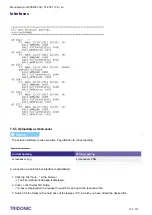
Page 106: ...e the same procedure to change the user interface layout ConfigData TestBook or the xetouch software 7 5 4 TA_mobile Webpage TA_mobile Webpage gives you the possibility to control Light from Android and Apple devices over WLAN This page can be edited and customised Supported Commands Goto Scene1 16 OFF DAPxxx 0 255 UP Down Startsequenz Stopsequenz Resetsequenz Grup 1 16 Grup not supported for scen...

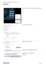
Page 107: ...Ethernet Type the IP address followed by TAmobile htm in your Web Browser Attention The xetouch software is case sensitive Pay attention to correct spelling You will see the TA_mobile Webpage On this Page you can recall Scene 1 3 and Switch the lights off How to Editing the page example Google Chrome ...

Page 108: ...021 2 9 en Interfaces c 108 118 Right click in the black area and select view page source You will see the source code Right click and select Save as Select save as type Webpage HTML Only Rename the File to TAmobile htm and save it ...

Page 109: ...mand for Scene 1 coords 163 82 320 132 is the Field Position Now you can change the Command or the coordinates for Field Scene1 in the source code Example customised TA_mobile Here you can see a customised TA_mobile graphic Each field has a different command Save the Graphic as TAmobile jpg Attention The xetouch software is case sensitive Pay attention to correct spelling Here you can see the sour...

Page 110: ... htm and TAmobile jpg 7 5 5 Rename Groups Scenes Sequences Schedules It is possible to rename groups scenes sequences and schedules directly on your Computer How to over Ethernet Connect over Ethernet to your x e touchPANEL Select more to see the File Up Download Page Select get text file containing all name strings ...

Page 111: ...touch software is case sensitive Pay attention to correct spelling Search and open the saved file e g in Notepad Now you can edit the names of Groups Scenes Schedules Sequences Each Application has his own template and has to be downloaded separately When you have changed the Names save the File xetouchPANELNames txt Select on the File Up Download Page choose File ...

Page 112: ...Manual x e touchPANEL 02 01 2021 2 9 en Appendix c 112 118 Select upload You will then see that the file upload was OK Select return to main page Result Changed Name of Group 1 ...

Page 113: ... of DALI lines 2 Device addresses in EMERGENCY operating mode 60 for each DALI line 120 Device addresses in the BASIC COLOUR or PLUG operating mode 64 for each DALI line 128 Dimensions L x W x H 200 x 150 x 20 mm Permissible ambient temperature 0 50 C Weight 0 92 kg Fastening distance D 155 mm Protection class IP 20 Protection class SK I Screen Touchpanel 7 800 x 480 64k colours The x e touchPANEL...

Page 114: ...1 2021 2 9 en Appendix c 114 118 8 2 Circuit diagrams 8 2 1 Circuit diagram EMERGENCY Application 8 2 2 Circuit diagram Basic Colour Plug Application I NOTICE The x e touchPANEL requires a separate bus supply for each DALI line ...

Page 115: ... connections 8 3 1 Name of x e touchPANEL IP Address MAC Address Subnet Mask Default Gateway Annotation 8 3 2 Name of x e touchPANEL IP Address MAC Address Subnet Mask Default Gateway Annotation 8 3 3 Name of x e touchPANEL IP Address MAC Address Subnet Mask Default Gateway Annotation ...

Page 116: ...EL 02 01 2021 2 9 en Appendix c 116 118 8 3 4 Name of x e touchPANEL IP Address MAC Address Subnet Mask Default Gateway Annotation 8 3 5 Name of x e touchPANEL IP Address MAC Address Subnet Mask Default Gateway Annotation ...

Page 117: ...efined Click on the Main menu symbol The Main menu is displayed Ensure that each device is only assigned to one group Click on the Addressing grouping button Click on the Folder button and check all groups one after another Ensure that the device is assigned to a group Change the grouping as required Ensure that a crossed network cable was used for a point to point connection x e touchPANEL direct...

Page 118: ...ates http www tridonic com com en certificates asp _ Tridonic software http www tridonic com com en software asp _ x e touchPANEL software http www tridonic com com en software x e touchpanel asp _ em LINK software http www tridonic com com en software em link asp _ Guarantee conditions http www tridonic com com en guarantee asp _ Data sheets http www tridonic com com en data sheets asp _ Environm...

Reviews: