


Chapter 14: Client DHCP Configuration
TR0190 Rev. B1
94
>
use sys
sys>
set dhcp.relay.enable=yes
sys
> set l2.client_mac_fwd=yes
In the example below, the central DHCP server and next WAN router reside on the same
segment to which the EL-500’s Ethernet interface is connected.
>
use sys
sys>
set dhcp.relay.server=192.168.5.2
sys>
set dhcp.relay.gateway=192.168.5.1
The example below shows how to set the DHCP mode parameters for the wlan1 and wlan2
interfaces.
>
use wlan1
wlan1>
set dhcp=server
wlan1>
set wlan1.dhcp.relay.enable=yes
>
use wlan2
wlan2>
set dhcp=server
wlan1>
set wlan2.dhcp.relay.enable=yes
To disable distribution of centralized DHCP addresses on an interface, set the interface’s
‘dhcp.role’ parameter to ‘none’ as shown below.
>
use wlan3
wlan3> set dhcp=none
The Client Address Space value is set with the ‘dhcp.relay.dhcp_subnet’ parameter in the ‘sys’
interface. This value should be a class A, B, or, C subnet specified using CIDR notation as
shown in the example below.
>
use sys
sys>
set dhcp.relay.dhcp_subnet=192.168.5.0/24
The Base Value, which sets the IP address of client access interfaces on an EL-500, is set
through the ‘dhcp.relay.base’ parameter in the ‘sys’ interface.
> use sys
sys>
set dhcp.relay.base=192.168.5.3
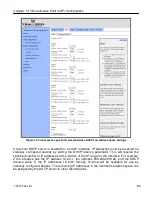
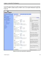
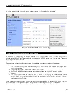
Web GUI
Centralized DHCP mode can be enabled via the web interface on the “DHCP Relay” sub-tab
under the “DHCP” tab on the “System Parameters” page (see Figure 46). The external DHCP
server IP address, the gateway router address, the Client Address Space parameter, and the
Base Value can also be set on this page. The DHCP mode parameters for all client access
interfaces can be set on the “DHCP” sub-tab under the “DHCP” tab on the “System
Parameters” page. Set the DHCP mode to “central server” for all interfaces whose client
devices should receive addresses from the central DHCP server.
Summary of Contents for EL-500
Page 20: ...Chapter 3 Using the Web Interface TR0190 Rev B1 20 Figure 8 Rebooting the EL 500...
Page 68: ...Chapter 11 Ethernet Interface Configuration TR0190 Rev B1 68 Figure 38 Wired DHCP settings...
Page 108: ...Chapter 16 Controlling Access to the ER 1000 TR0190 Rev B1 108 Figure 50 VAP ACL configuration...


