Chapter 8: Mode of Operation
TR0190 Rev. B1
45
8
Mode of Operation
The EL-500 can be configured to operate in either routed or bridge mode. In routed mode, all
communication is managed at the IP (layer 3) level, with the EL-500 acting as a router. In
bridge mode, all communication across the EL-500 is managed at the MAC (layer 2) level, with
the EL-500 acting as a switch.
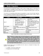
The choice of the operating mode affects the availability of many of the EL-500’s features,
which is reflected in the web GUI options available when a particular mode is chosen. Table 5
summarizes the feature differences between the two modes
Feature
Bridge Mode
Routed mode
DHCP
•
The bridge interface can be
a DHCP client.
•
All DHCP requests from
client devices attaching to
the virtual APs must be
handled by a separate
device on the network
•
The wired interface can be a
DHCP client.
•
DHCP requests from client
devices attaching to the virtual
APs can be handled by a local
DHCP server on the EL-500 or
can be forwarded to a
centralized server
Splash pages
Not available
Available
Firewall
Custom firewall rules cannot be
added
Custom firewall rules can be
added
Wired and virtual AP
IP addresses
The interfaces do not have IP
addresses
IP addresses must be assigned to
the interfaces
QoS
Not available
Available
DNS proxy
Not available
Available
Table 5. Feature differences between bridge and routed mode
When switching to bridge mode, all the IP addresses for virtual access points
‘wlan1 – 4’ and the wired interface will be disabled. A bridge interface will be
created to provide IP access to the EL-500 in bridge mode. By default the
address of this interface will be set to
<LAN prefix first octet>.<node ID>
.1.1 It
is recommended that an IP address is explicitly set for the bridge interface
when switching to bridge mode. See section 12.1 for instructions on how to
set the bridge interface parameters.
Certain web GUI pages are only available when the device is configured for bridge mode
operation. These pages are:
•
“L2 Bridge” in the main navigation bar
•
“Bridging” tab on the “Status” page
Summary of Contents for EL-500
Page 20: ...Chapter 3 Using the Web Interface TR0190 Rev B1 20 Figure 8 Rebooting the EL 500...
Page 68: ...Chapter 11 Ethernet Interface Configuration TR0190 Rev B1 68 Figure 38 Wired DHCP settings...
Page 108: ...Chapter 16 Controlling Access to the ER 1000 TR0190 Rev B1 108 Figure 50 VAP ACL configuration...


