Chapter 14: Client DHCP Configuration
TR0190 Rev. B1
93
14.2.1
Support for Clients with Static IP Addresses
When using centralized DHCP server mode for a client access interface, client devices
connected to that interface can be assigned static addresses within the client address space.
However, for these client devices to roam successfully across EL-500s and third party access
point bridges connected to the same LAN, they must employ duplicate address detection by
sending out ARP requests for their own IP address. Windows-based devices support this
requirement. Please contact the client device manufacturer if you are unsure if your client
device meets this requirement.
14.2.2
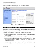
Configuring the EL-500s
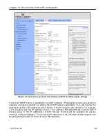
When operating in centralized DHCP server mode, each EL-500 client access interface that is
to serve DHCP addresses from the centralized server must be explicitly configured to use
centralized DHCP server mode. The EL-500s with client access interfaces in centralized
DHCP server mode must also use the same centralized DHCP server. The IP address of the
central DHCP server is set with the DHCP relay server parameter. The server must be
reachable through the EL-500’s Ethernet interface.
A gateway router IP address must be entered. This will be supplied to DHCP client devices as
their gateway. This IP address can be the same as for the DHCP server, but need not be.
Each client access interface on the EL-500 that is to support centralized DHCP server mode
must have its DHCP mode set to “server” for it to support relay of IP addresses to client
devices from a central DHCP server. It is possible to disable DHCP address assignments to
client devices on a per-interface basis and have them use static IP addresses instead.
The address space that is to be used for the wireless client devices is a subnet specified with
the Client Address Space parameter. The value must be specified in CIDR notation (a subnet
and its size separated by a ‘/’), e.g. ‘192.168.5.0/24’
The IP addresses of the EL-500’s client access interfaces (wlan1-4) need to be manually
assigned. This is done by setting the Address Base parameter, which is assigned to the first
enabled client access interface. Addresses for the remaining client access interfaces are
determined by successively incrementing the Base Address by one.
Layer 2 emulation must also be enabled when operating in centralized DHCP server mode.
This setting is located on the “System” tab of the “System” page of the web interface. See
section 19.2 for more information on layer 2 emulation mode.
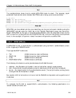
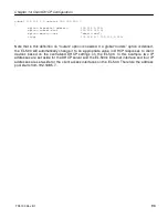
CLI
Centralized DHCP mode is enabled using the ‘dhcp.relay.enable’ and ‘l2.client_mac_fwd’
parameters in the ‘sys’ interface as shown in the example below.
Summary of Contents for EL-500
Page 20: ...Chapter 3 Using the Web Interface TR0190 Rev B1 20 Figure 8 Rebooting the EL 500...
Page 68: ...Chapter 11 Ethernet Interface Configuration TR0190 Rev B1 68 Figure 38 Wired DHCP settings...
Page 108: ...Chapter 16 Controlling Access to the ER 1000 TR0190 Rev B1 108 Figure 50 VAP ACL configuration...

