Chapter 10: Client Addressing Schemes
TR0190 Rev. B1
64
10.2 Explicit Addressing Scheme
When using the explicit addressing scheme, the IP parameters for each interface can be
specified manually on the “Wireless Interface” page.
When specifying the IP addresses and subnet sizes for the client access interfaces, the
following rules should be followed:
•
Specify IP address and subnet combinations that do not lead to misalignment, e.g.
10.0.0.4/24 is not a properly aligned address/subnet size combination.
•
Do not specify subnets that are in the following ranges:
o
169.254.0.0/16
o
127.0.0.0/8
•
Each subnet specified for a client access interface must not overlap with that of any
other client access interface on the device.
•
Do not specify any subnets for client access interfaces that overlap with subnets outside
the device that you want client devices to be able to connect to.
Do not specify a gateway IP address for any of the client access interfaces
when operating using the explicit addressing scheme. This field should be left
blank for each interface.
If an address space is not defined for a client access interface when operating in explicit
addressing mode, a default address space will be defined with the following parameters
•
IP address:
<first octet of LAN prefix>.<node ID>.<virtual AP number (1-4)>.1
•
IP netmask: 255.255.255.0
CLI
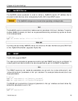
Set the ‘implicit.enable’ parameter in the ‘mesh0’ to ‘no’ interface to select the explicit
addressing scheme. The example below demonstrates this.
>
use mesh0
sys>
set implicit.enable=no
See section 13.3 for instructions on how to set the IP addresses for the client access interfaces
when using the explicit addressing scheme.
Web GUI
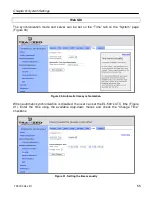
The addressing scheme is set with the “Implicit Addressing” drop-down menu on the “System”
tab of the “System” page (see Figure 34). Set this to “disabled” to use the explicit addressing
scheme.
Summary of Contents for EL-500
Page 20: ...Chapter 3 Using the Web Interface TR0190 Rev B1 20 Figure 8 Rebooting the EL 500...
Page 68: ...Chapter 11 Ethernet Interface Configuration TR0190 Rev B1 68 Figure 38 Wired DHCP settings...
Page 108: ...Chapter 16 Controlling Access to the ER 1000 TR0190 Rev B1 108 Figure 50 VAP ACL configuration...


