Gives the calculated/estimated thermal load on the
motor. 100% is the cut-out limit. See also parameter
128
Thermal motor protection
.
Thermal load INV [%], parameter 527:
Gives the calculated/estimated thermal load on the
frequency converter. 100% is the cut-out limit.
Digital input, parameter 528:
Gives the signal status from the 5 digital inputs (18,
19, 27, 29 and 33). Input 18 corresponds to the bit on
the extreme left. '0' = no signal, '1' = connected signal.
Terminal 53 analogue input [V], parameter 529:
Gives the voltage value for the signal on terminal 53.
Terminal 60 analogue input [mA], parameter 531:
Gives the present value for the signal on terminal 60.
Pulse reference [Hz], parameter 532:
Gives a pulse frequency in Hz connected to terminal
33.
External reference, parameter 533:
Gives the sum of external references as a percentage
(sum of analogue/pulse/serial communication) in the
range from Minimum reference, Ref MIN to Maxi-
mum reference, Ref MAX.
Status word, parameter 534:
Gives the present status word for the frequency con-
verter in Hex.
Bus feedback 1, parameter 535:
Allows writing of a bus feedback value which will
then form part of the feedback handling.
Inverter temperature, parameter 537:
Gives the present inverter temperature on the fre-
quency converter. The cut-out limit is 90-100 °C, with
cut back in at 70
±
5
°
C.
Alarm word, parameter 538:
Gives in Hex code which alarm is on the frequency
converter. See
Warning word, extended status word
and alarm word.
Control word, parameter 539:
Gives the present control word on the frequency con-
verter in Hex.
Warning word, parameter 540:
States whether there is a warning on the frequency
converter in Hex. See
Warning word, extended status
word and alarm word.
Extended status word, parameter 541:
States whether there is a warning on the frequency
converter in Hex code. See
Warning word, extended
status word and alarm word.
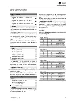
Pulse count, parameter 544:
This parameter can be read out via the LCP display
(009-012). When you run with counter stop, this pa-
rameter enables you, either with or without reset, to
read the number of pulses registered by the device.
The highest frequency is 67.6 kHz, while the lowest is
5 Hz. The counter is reset when counter stop is re-
started.
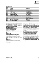
560
N2 Override release time
Value:
1 - 65534 (OFF) sec.
OFF
Function:
In this parameter, the maximum time is set which is
expected to pass between the receipt of two N2 tele-
grams in a row. If this time is exceeded, the serial
communication is assumed to have stopped and all
points in the N2 point-map which are overridden will
be released in the order below:
1.
Release Analog Outputs from point address
(NPA) 0 to 255.
2.
Release Binary Outputs from point address
(NPA) 0 to 255.
3.
Release Internal Floating Points from point ad-
dress (NPA) 0 to 255.
4.
Release Internal Integer Points from point ad-
dress (NPA) 0 to 255.
5.
Release Internal Byte points from point address
(NPA) 0 to 255.
Description of choice:
Set the required time.
TR1
2800
Series
VFD
77
Programming
Summary of Contents for VarioTrane TR1 2800 Series
Page 2: ...T TR R1 1 2 28 80 00 0 S Se er ri ie es s V VF FD D 1 1...
Page 3: ...2 2 T TR R1 1 2 28 80 00 0 S Se er ri ie es s V VF FD D...
Page 4: ...TR1 2800 Series VFD 3...
Page 7: ...6 TR1 2800 Series VFD...
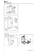
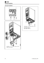
Page 87: ...Illustration 5 7 192H4719 Illustration 5 8 192H4720 86 TR1 2800 Series VFD...
Page 95: ...Branch Circuit Protection Short circuit protection 94 TR1 2800 Series VFD...
Page 107: ...All about TR1 2800 Series VFD 106 TR1 2800 Series VFD...


