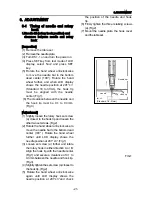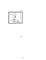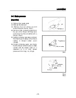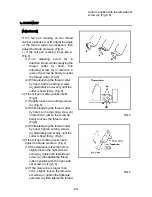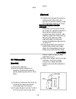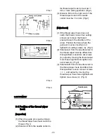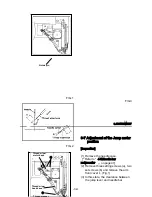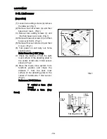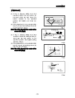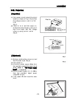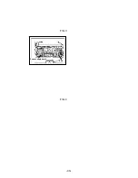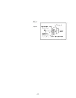
reciprocator must be 0.5mm. (Fig.2)
[Adjustment]
(1)
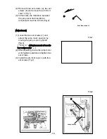
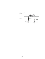
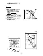
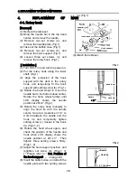
Loose the two setting screws (c) and
adjust the jump motor position by
moving the jump motor right/left.
(Fig.3)
[『refer to “ 4-5.Needle bar
reciprocator” 』 on page 41]
(2) After adjusting, locate the jump motor
at its highest position and tighten two
setting screws.
(3) Install the arm front cover L with five
setting screws. (Fig.1)
FIG.1
FIG.2
(a)
(b)
Arm front cover L
(c)
Jump motor
0.5mm
Jump lever
Needle bar
reciprocator
-33-
Summary of Contents for ESP9000
Page 1: ...SERVICE MANUAL Embroidery Machine ESP9000 15 needles...
Page 2: ......
Page 13: ...FIG 3 48...
Page 24: ...FIG 4 59...
Page 36: ...Connection of connector CN 10 Must be connected correctly Replace See P 47 CN10 11...
Page 40: ...Picker height C 7 9 mm when piker solenoid is ON Adjust See P 27 15...
Page 58: ...FIG 2 FIG 3 201 3 0 1 0 3 mm 22...
Page 63: ...FIG 4 e Drive arm FIG 5 27...
Page 70: ...FIG 3 34...
Page 72: ...FIG 2 FIG 3 201 3 0 1 0 3 mm 22...
Page 74: ...FIG 2 FIG 3 Needle bar Stopper Needle bar Connecting stud 24...
Page 77: ...FIG 4 e Drive arm FIG 5 27...
Page 84: ...FIG 3 34...
Page 86: ...FIG 4 31...
Page 88: ...FIG 4 33...
Page 90: ...FIG 2 35...
Page 93: ...2 a Sensor arm 3 38...
Page 95: ...FIG 3 FIG 4 VR6 Power supply board 40...
Page 97: ...FIG 3 FIG 4 0 5 to 0 8mm 0 2mm or less Hook support hook support 37...
Page 100: ...FIG 4 40...
Page 103: ...FIG 2 Needle bar c Top dead center stopper needle bar connecting stud FIG 3 43...
Page 105: ...FIG 5 45...
Page 111: ...Printed in Japan 2002 8...

