1.SPECIFICATIONS
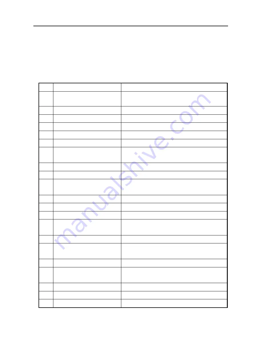
1.SPECIFICATIONS
ESP9000
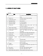
No
Item
Specifications
1
Type of stitch
Lock stitch type sewing machine (for automatic embroidery
only)
2
Rotary hook
Vertical 2 revolution type (eccentric)
3
Thread take-up lever
Cam take-up lever
4
Needle bar stroke
50 ± 0.2 mm
5
Number of needles
15 (auto changing)
6
Applicable needles
Organ DB×K5Z #11
7
Presser foot
Needle bar linked driving system (with noise
reduction mechanism)
8
Bobbin thread winding
Semi-auto winding (auto return, also stop)
9
Thread trimming method
Horizontal reciprocation (motor drive)
10 Thread wiper
Motor drive sliding type (with thread retaining
mechanism)
11 Picker method
Picking at start, end of sewing and cutting thread
12 Stitch speed
1,200spm maximum (800spm standard)
13 Embroidery area
360 mm long × 500 mm wide
14 Embroidery
control
and
indication
Touch switch control with LED/LED displays
15 Stitch memory
280,000 stitches
16 Memory back-up
Memory saved during operation and after power off;
kept for 4 weeks
17 Weight
80 ± 1kg (without table)
18 Machine oil
High grease NX 2, molybdenum grease NO 2, SF oil
(multi-grade)
19 Drive motor
AC servo motor (machine revolution)
20 Control motor
AC servo motor (X axis, Y axis)
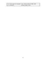
21 Needle thread failure detection
Rotary detection system (photo sensor)
-1-
Summary of Contents for ESP9000
Page 1: ...SERVICE MANUAL Embroidery Machine ESP9000 15 needles...
Page 2: ......
Page 13: ...FIG 3 48...
Page 24: ...FIG 4 59...
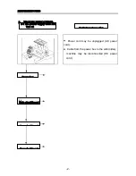
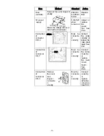
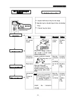
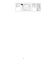
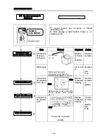
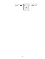
Page 36: ...Connection of connector CN 10 Must be connected correctly Replace See P 47 CN10 11...
Page 40: ...Picker height C 7 9 mm when piker solenoid is ON Adjust See P 27 15...
Page 58: ...FIG 2 FIG 3 201 3 0 1 0 3 mm 22...
Page 63: ...FIG 4 e Drive arm FIG 5 27...
Page 70: ...FIG 3 34...
Page 72: ...FIG 2 FIG 3 201 3 0 1 0 3 mm 22...
Page 74: ...FIG 2 FIG 3 Needle bar Stopper Needle bar Connecting stud 24...
Page 77: ...FIG 4 e Drive arm FIG 5 27...
Page 84: ...FIG 3 34...
Page 86: ...FIG 4 31...
Page 88: ...FIG 4 33...
Page 90: ...FIG 2 35...
Page 93: ...2 a Sensor arm 3 38...
Page 95: ...FIG 3 FIG 4 VR6 Power supply board 40...
Page 97: ...FIG 3 FIG 4 0 5 to 0 8mm 0 2mm or less Hook support hook support 37...
Page 100: ...FIG 4 40...
Page 103: ...FIG 2 Needle bar c Top dead center stopper needle bar connecting stud FIG 3 43...
Page 105: ...FIG 5 45...
Page 111: ...Printed in Japan 2002 8...

