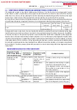


FI7187
Z17004
C
B
A
OPEN
Sensor
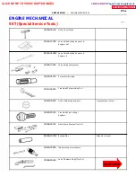
Fig. 1
ECU
1
2
1
2
1
2
2
1
Z17005
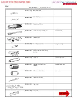
Fig. 2
Sensor
ECU
C
B
A
1
2
1
2
1
2
Z17807
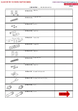
Fig. 3
Sensor
ECU
C
A
1
2
1
2
1
2
2
1
B2
B1
--
INTRODUCTION
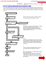
HOW TO TROUBLESHOOT ECU CONTROLLED
SYSTEMS
IN--23
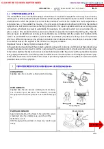
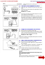
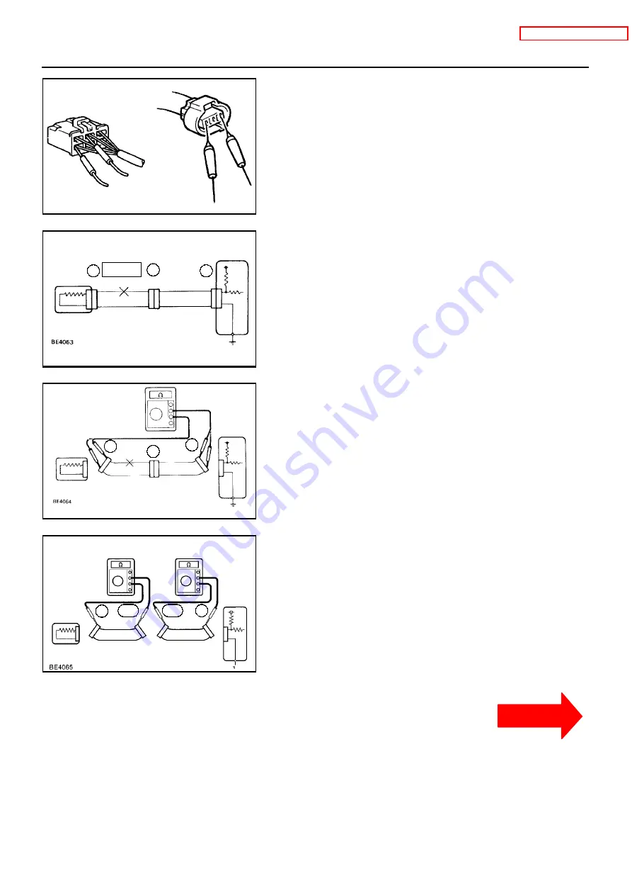
5 . CO NNE CTO R HANDLI NG
When inserting tester probes into a connector, insert them from
the rear of the connector. When necessary, use mini test leads.
For water resistant connectors which cannot be accessed from
behind, take good care not to deform the connector terminals.
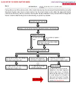
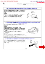
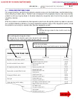
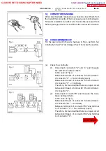
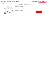
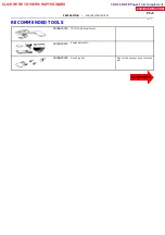
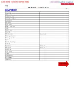
6 . CHE CK O P E N CI RCUI T
For the open circuit in the wire harness in Fig.1, perform ”(a)
Continuity Check” or ”(b) Voltage Check” to locate the section.
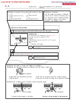
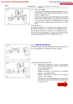
(a)
Check the continuity.
(1)
Disconnect connectors ”A” and ”C” and measure
the resistance between them.
In the case of Fig.2,
Between terminal 1 of connector ”A” and terminal 1
of connector ”C”
→
No continuity (open)
Between terminal 2 of connector ”A” and terminal 2
of connector ”C”
→
Continuity
Therefore, it is found out that there is an open circuit
between terminal 1 of connector ”A” and terminal 1
of connector ”C”.
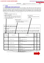
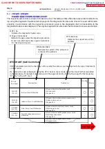
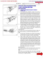
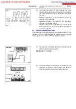
(2)
Disconnect connector ”B” and measure the resis-
tance between them.
In the case of Fig.3,
Between terminal 1 of connector ”A” and terminal 1
of connector ”B1”
→
Continuity
Between terminal 1 of connector ”B2” and terminal
1 of connector ”C”
→
No continuity (open)
Therefore, it is found out that there is an open circuit
between terminal 1 of connector ”B2” and terminal
1 of connector ”C”.
CLICK HERE TO VIEW CHAPTER INDEX
Pages From Supplement
3RZ-F,3RZ-FE


