


DI--86
--
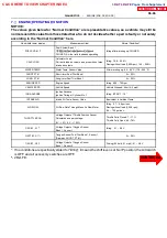
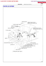
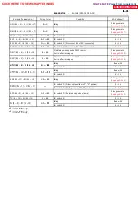
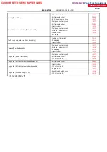
DIAGNOSTICS
ENGINE (2RZ--FE, 3RZ--FE)
Hand--held tester display
Measurement Item
Normal Condition*
INJECTOR
Fuel injection time for cylinder No.1
Idling: 2.5
∼
4.3 ms
ISC DUTY RATIO
Intake Air Control Valve Duty Ratio
Opening ratio rotary solenoid type IAC valve
Idling: 24.8
∼
50.0%
STARTER SIG
Starter Signal
Cranking: ON
CTP SW
Closed Throttle Position Switch Signal
Throttle Fully Closed: ON
A/C SIG
A/C Switch Signal
A/C ON: ON
STOP LIGHT SW
Stop Light Switch Signal
Stop light switch ON: ON
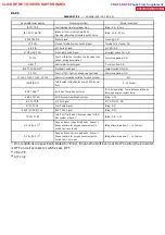
FC IDL
Fuel Cut Idle: Fuel cut when throttle valve fully
closed, during deceleration
Fuel cut operating: ON
NSW *
2
Neutral start switch signal
P or N position: ON
ELECT LOAD SIG*
2
Electrical Load Signal
Taillight switch ON: ON
FC TAU
Fuel Cut TAU: Fuel cut during very light load
Fuel cut operating: ON
CYL#1, CYL#2, CYL#3, CYL#4
Abnormal revolution variation for each cylinder
0%
IGNITION *
1
Total number of ignition for every 1,000 revolu-
tions
0
∼
2,000 rpm
EGRT GAS *
1
EGR Gas Temp. Sensor Value
EGR not operating: Temp. between intake air
temp. and engine coolant temp.
EGR SYSTEM
EGR System Operating Condition
Idling: OFF
A/C CUT SIG
A/C Cut Signal
A/C S/W OFF: ON
FUEL PUMP
Fuel Pump Signal
Idling: ON
EVAP (PURGE) VSV
EVAP VSV Signal
Idling: OFF
TOTAL FT B1
Total Fuel Trim Bank 1: Average value for fuel
trim system of bank 1
Idling: 0.8
∼
1.2 V
O2 LR B1, S1 *
1
Oxygen Sensor Lean Rich Bank 1, Sensor 1
Response time for oxygen sensor output to
switch from lean to rich
Idling after warmed up: 0
∼
1,000 msec.
O2 RL B1, S1 *
1
Oxygen Sensor Rich Lean Bank 1, Sensor 1
Response time for oxygen sensor output to
switch from rich to lean
Idling after warmed up: 0
∼
1,000 msec.
∗
: If no conditions are specifically stated for ”ldling”, it means the shift lever is at N or P position, the A/C switch
is OFF and all accessory switches are OFF.
*
1
2RZ--FE:
*
2
A/T only
CLICK HERE TO VIEW CHAPTER INDEX
Pages From Supplement
3RZ-F,3RZ-FE


