STE 73995
– 31 –
TRANSPORTATION AND INSTALLATION MANUAL
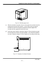
Fig. 2.14 Removing upper cover
(c) When the controller is mounted on the rack, the weight of the controller should be
supported with the legs of the controller. Screw holes for rack-mounting the
controller are used for securing the controller panel, and the weight of the
controller cannot be supported only with the screws.
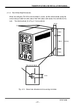
(d) On the front of the controller, a clearance of approx. 130 mm should be provided
for connecting the connector of the teach pendant. Even if the teach pendant is
not used, a clearance of approx. 50 mm is required for connecting a dummy plug.
3 5
1 3 0
Fig. 2.15 Clearance of controller front side
Summary of Contents for TH180
Page 11: ...STE 73995 10 TRANSPORTATION AND INSTALLATION MANUAL Fig 1 3 Robot package TH180 ...
Page 21: ...STE 73995 20 TRANSPORTATION AND INSTALLATION MANUAL Fig 2 4 External view of TH350A T robot ...
Page 80: ...STE 73995 79 TRANSPORTATION AND INSTALLATION MANUAL APPROVED BY CHECKED BY PREPARED BY ...

