


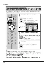


Playback
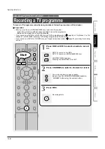
Recording
Editing
Others
Introduction
Function
setup
6
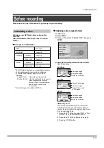
Picture ratio when recording DVD-Video
Make this setting when this timer programme is
(or will be) onto DVD-R/RW (Video mode).
Video mode cannot record a title which contains
both 4:3 pictures and 16:9 pictures.
4:3: Aspect ratio is fixed to 4:3 to record.
16:9: Aspect ratio is fixed to 16:9 to record.
7
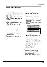
Auto chapter division when there is no sound
This feature automatically creates divisions for
chapters when no audio (no audible sound)
portion is found.
For example, when you have recorded a
programme of music clips, you can use this
feature to jump to the beginning of a clip during
playback.
Off: This feature is disabled.
On: Division for chapters are created when no
audio portion is found.
Notes
• Division for chapters may not be created, depending
on the contents of the programme or the condition of
no audio portion, or it may be created at different
positions. A division for a chapter may be created
within a music clip.
• Depending on the specification made for the
recording sound level, a division for a chapter may
not be created or it may be created at different
positions.
• Setting “On” may create chapters, and their number
may reach the maximum allowed. At that point, no
more chapters can be created. In this case, decrease
the chapters, for example, combining chapters.
• This feature is not available on DVD-R/RW discs
(Video mode). To create chapters automatically
during recording on DVD-R/RW disc (Video mode),
set “DVD-Video chp div”.
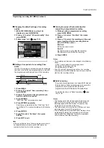
8
Chapter division when DVD-Video
Make this setting when this timer programme is
(or will be) onto DVD-R/RW (Video mode).
This feature creates chapters automatically while
recording. Chapters enables skipping play of the
recorded disc.
Off: This feature is disabled.
5 min / 10 min / 15 min / 20 min:
Select the interval of chapters.
Notes
• If a number of chapters reaches the maximum, which
may vary depending on the disc condition, no more
chapters are created.
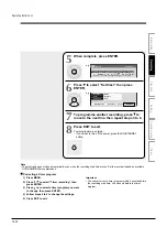
9
PDC
To activate the PDC recording feature to record
the programme or not.
PDC (Programme Delivery Control System)
Programme PDC is a system of telling the recorder
when a programme actually starts. Typically, when
you want to record programme you will tell the
recorder to start recording, probably, five minutes
before the advertized starting time of the
programme and to finish ten minutes or so after the
programme is due to finish. So even if the
programme starts early or finishes late you will
normally still get to see what you wanted to record.
However when live programme over-run or the
day’s television schedule is changed from that
advertized, you may miss the desired programme
which may have been delayed or even cancelled
and the recorder will record the programme even if
it is two or more hours late. With PDC, you enter
the exact start time and the recorder will wait until
the signal is sent to confirm the programme is
starting and the recorder will record the programme
even if it is two or more hours late.
Off: This feature is disabled.
On: This feature is enabled.
Note
• When setting “Ch” to “L”, “AV1” or “AV2”, this function
is not available.
Operating Instructions
12-22
Summary of Contents for RD-XS24SB
Page 10: ...Product Specification 2 4 MEMO ...
Page 12: ...3 2 Software Update MEMO ...
Page 20: ...4 8 Disassembly and Reaasembly MEMO ...
Page 34: ...Troubleshooting 5 14 MEMO ...
Page 35: ...6 1 6 Exploded View and Parts List 6 1 Cabinet Assembly Page 6 2 ...
Page 38: ...Exploded Views and Parts List 6 4 MEMO ...
Page 50: ...Electrical Parts List 7 12 MEMO ...
Page 160: ...Operating Instructions 12 110 MEMO ...
Page 173: ...1 1 SHIBAURA 1 CHOME MINATO KU TOKYO 105 8001 JAPAN ...
Page 177: ...Block Diagrams 8 3 8 2 Digital Block Diagram ...
Page 180: ...Block Diagrams 8 6 8 5 AIC01 MSP3417 Block Diagram ...
Page 181: ...Block Diagrams 8 7 8 6 AIC02 AIC07 MC14052 Block Diagram ...
Page 182: ...Block Diagrams 8 8 8 7 AIC03 AK5357 Block Diagram ...
Page 183: ...Block Diagrams 8 9 8 8 AIC04 PCM1753 Block Diagram ...
Page 184: ...Block Diagrams 8 10 8 9 KIC01 PT6961 Block Diagram ...
Page 185: ...Block Diagrams 8 11 8 10 MIC01 78F4225 Block Diagram ...
Page 187: ...Block Diagrams 8 13 8 12 SIC01 MM1647 Block Diagram ...
Page 188: ...Block Diagrams 8 14 8 13 VIC01 74HC4051 Block Diagram ...
Page 189: ...Block Diagrams 8 15 8 14 VIC05 MM1568 Block Diagram ...
Page 190: ...Block Diagrams 8 16 MEMO ...
Page 191: ...9 Wiring Diagram 9 1 ...
Page 192: ...Wiring Diagram 9 2 MEMO ...
Page 194: ...PCB Diagrams 10 2 10 1 S M P S PCB COMPONENT SIDE ...
Page 195: ...PCB Diagrams 10 3 CONDUCTOR SIDE ...
Page 196: ...PCB Diagrams 10 4 10 2 Main PCB COMPONENT SIDE ...
Page 198: ...PCB Diagrams 10 6 10 3 Jack PCB COMPONENT SIDE ...
Page 199: ...PCB Diagrams 10 7 CONDUCTOR SIDE ...
Page 200: ...PCB Diagrams 10 8 10 4 Key PCB COMPONENT SIDE CONDUCTOR SIDE ...
Page 202: ...Schematic Diagrams 11 2 11 1 S M P S SMPS PCB ...
Page 203: ...Schematic Diagrams 11 3 11 2 Main Main PCB ...
Page 204: ...Schematic Diagrams 11 4 11 3 Audio Jack PCB ...
Page 205: ...Schematic Diagrams 11 5 11 4 Video Jack PCB ...
Page 206: ...Schematic Diagrams 11 6 11 5 AV switch Scart Jack PCB ...
Page 207: ...Schematic Diagrams 11 7 11 6 Tuner Front in Connection Jack PCB ...
Page 208: ...Schematic Diagrams 11 8 11 7 Micom Jack PCB ...
Page 209: ...Schematic Diagrams 11 9 11 8 Key Key PCB ...
Page 210: ...Schematic Diagrams 11 10 MEMO ...


