


Operating Instructions
12-90
Editing
Function
setup
Others
Introduction
Recording
Playback
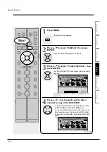
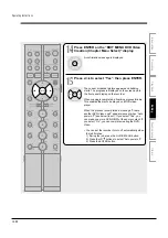
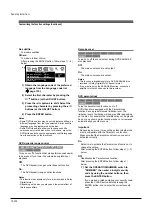
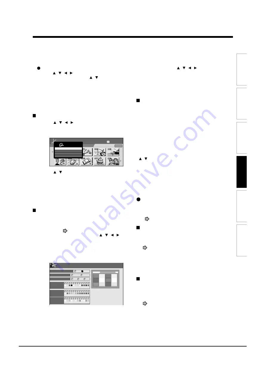
To delete a captured image
Press
/ / / to select an image to delete then
press QUICK MENU. Press / to select “Delete
Menu” then press ENTER. Follow the message to
operate.
To delete all captured images, select “Delete all
Menus”.
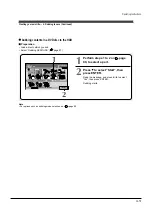
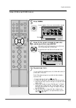
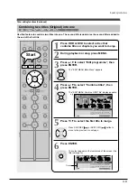
Cancelling selection of an item
1) Press / / / to select an item then press
QUICK MENU.
The Quick Menu appears.
2) Press / to select “Cancel Selected Title” (or
“Clear All Selected Items” for cancelling
selection of all items at a time).
3) Press ENTER.
The selected item disappears.
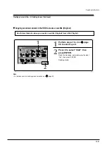
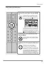
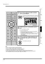
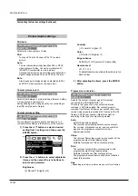
Selecting colour options on menus
Several options are available: a translucent
background for better legibility, character colour and
cursor colour selections.
1) At step 11 (
page 102), go to the next page
and select a captured image by / / / ,
then press MODE.
The preview screen appears.
2) Press MODE.
A colour setting display appears.
HDD (VR)
HDD :
DVD-Video Create (Selected Items)
Original
Source: (VR)Title
E D I T
MENU
11
e.g.
Quick Menu
Cancel Selected Title
Title Information
Clear All Selected Items
Exit
A
A
A
B
B
DVD-Video Creation (color setting)
EDIT
MENU
e.g.
Back ground color
On
Off
White
Black
0.5
0.7
0.9
Color
Permeation Ratio
12
Character
color
Selecting
color
Selected
color
DO NOT
LEAVE HERE
LEAVE HERE
DO NOT
LEAVE HERE
DO NOT
DO NOT
LEAVE HERE
DO NOT
LEAVE HERE
DO NOT
LEAVE HERE
11
10
9
8
7
6
5
4
3
2
1
12
11
10
9
8
7
6
5
4
3
2
1
12
11
10
9
8
7
6
5
4
3
2
1
Set up the disc name, the
title name or page numer
on upper side of the screen,
OR the letter color of the
title name, the chapter
name and the time beside
the thumbnail.
3) Set each item by / / / , referring to the
guidance on the right half of the display, finally
press RETURN to exit.
The preview screen returns.
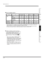
If a message appears while selecting a part
You may receive a message, such as “Selection of
Writing Test in the next option setting is recommended
to check whether Aspect Ratio coexists”. If a copy-
prohibited content is included, or if the aspect ratio is
changed meanwhile, cancel the selection. If you are
not sure, select “Writing Test” (“Parts Test” or “All
Test”).
Note
• Depending on selection or condition of items, copying may
result in failure. If a message appears, be sure to, prior to
step 8, press the QUICK MENU button. Then press the
/ buttons to select “Cancel selected title”, and press
the ENTER button. If you do not do this and continue the
copying process, an error may occur and the disc will be
rendered useless.
Playing a created DVD-Video
You can play the DVD-R/RW (Video mode) in the same
manner as you would play a DVD video disc.
See
page 56.
If you want to correct the contents of a DVD-RW
(Video mode) after the DVD-Video creation
procedure
Cancel the finalization of the DVD-RW (Video mode)
(
page 93).
It is possible only on DVD-RW (Video mode) recorded
on this recorder.
After cancelling, you can delete titles. However, you
cannot re-use the whole disc, since only the last title
can restore the disc space.
If you want to delete all contents of a DVD-RW
(Video mode) after the DVD-Video creation
procedure
Load the DVD-RW into the recorder and initialize it,
then execute the procedure of DVD-Video creation
(
page 98).
Summary of Contents for RD-XS24SB
Page 10: ...Product Specification 2 4 MEMO ...
Page 12: ...3 2 Software Update MEMO ...
Page 20: ...4 8 Disassembly and Reaasembly MEMO ...
Page 34: ...Troubleshooting 5 14 MEMO ...
Page 35: ...6 1 6 Exploded View and Parts List 6 1 Cabinet Assembly Page 6 2 ...
Page 38: ...Exploded Views and Parts List 6 4 MEMO ...
Page 50: ...Electrical Parts List 7 12 MEMO ...
Page 160: ...Operating Instructions 12 110 MEMO ...
Page 173: ...1 1 SHIBAURA 1 CHOME MINATO KU TOKYO 105 8001 JAPAN ...
Page 177: ...Block Diagrams 8 3 8 2 Digital Block Diagram ...
Page 180: ...Block Diagrams 8 6 8 5 AIC01 MSP3417 Block Diagram ...
Page 181: ...Block Diagrams 8 7 8 6 AIC02 AIC07 MC14052 Block Diagram ...
Page 182: ...Block Diagrams 8 8 8 7 AIC03 AK5357 Block Diagram ...
Page 183: ...Block Diagrams 8 9 8 8 AIC04 PCM1753 Block Diagram ...
Page 184: ...Block Diagrams 8 10 8 9 KIC01 PT6961 Block Diagram ...
Page 185: ...Block Diagrams 8 11 8 10 MIC01 78F4225 Block Diagram ...
Page 187: ...Block Diagrams 8 13 8 12 SIC01 MM1647 Block Diagram ...
Page 188: ...Block Diagrams 8 14 8 13 VIC01 74HC4051 Block Diagram ...
Page 189: ...Block Diagrams 8 15 8 14 VIC05 MM1568 Block Diagram ...
Page 190: ...Block Diagrams 8 16 MEMO ...
Page 191: ...9 Wiring Diagram 9 1 ...
Page 192: ...Wiring Diagram 9 2 MEMO ...
Page 194: ...PCB Diagrams 10 2 10 1 S M P S PCB COMPONENT SIDE ...
Page 195: ...PCB Diagrams 10 3 CONDUCTOR SIDE ...
Page 196: ...PCB Diagrams 10 4 10 2 Main PCB COMPONENT SIDE ...
Page 198: ...PCB Diagrams 10 6 10 3 Jack PCB COMPONENT SIDE ...
Page 199: ...PCB Diagrams 10 7 CONDUCTOR SIDE ...
Page 200: ...PCB Diagrams 10 8 10 4 Key PCB COMPONENT SIDE CONDUCTOR SIDE ...
Page 202: ...Schematic Diagrams 11 2 11 1 S M P S SMPS PCB ...
Page 203: ...Schematic Diagrams 11 3 11 2 Main Main PCB ...
Page 204: ...Schematic Diagrams 11 4 11 3 Audio Jack PCB ...
Page 205: ...Schematic Diagrams 11 5 11 4 Video Jack PCB ...
Page 206: ...Schematic Diagrams 11 6 11 5 AV switch Scart Jack PCB ...
Page 207: ...Schematic Diagrams 11 7 11 6 Tuner Front in Connection Jack PCB ...
Page 208: ...Schematic Diagrams 11 8 11 7 Micom Jack PCB ...
Page 209: ...Schematic Diagrams 11 9 11 8 Key Key PCB ...
Page 210: ...Schematic Diagrams 11 10 MEMO ...


