


Recording
Playback
Editing
Function
setup
Others
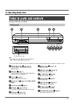
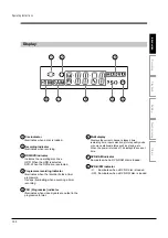
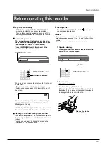
Introduction
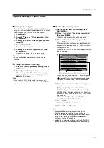
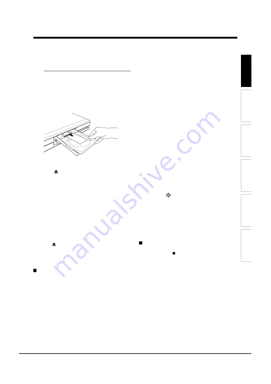
DVD-RAM disc with cartridge (TYPE1/TYPE2/TYPE4)
Single sided
Turn the printed side up, and insert the cartridge
into the tray frame following the direction of the
arrow on the cartridge.
Double sided
Turn the desired recording/playback side up, and
insert the cartridge into the tray frame following the
direction of the arrow on the cartridge.
3 Close the disc tray.
Press
on the front panel or the OPEN/CLOSE
button on the remote control.
Notes
• Use the button on the front panel or the remote control to
open and close the disc tray. Do not push or hold the disc
tray while it is moving. Doing so may cause the recorder to
malfunction.
• Do not insert a disc which is unplayable, or any object
other than a playable disc.
• Do not apply downforce to the disc tray. Doing so may
cause the recorder to malfunction.
• If the disc tray stops while closing, the mechanical
protection system of this recorder will open it. Do not force
it to close. Doing so may cause malfunction.
• If the disc tray will not open, turn the recorder off, and
press the
button on the front panel or the OPEN/
CLOSE button on the remote control. This may turn the
recorder on and open the disc tray. If it still won’t open,
contact your nearest TOSHIBA dealer.
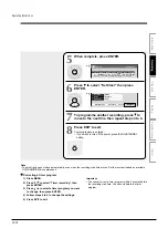
Turning the power off
Press ON/STANDBY on the front panel of the
recorder or on the remote control.
The “Unloading” icon appears at the top right corner of
the screen, and the display of the front panel shows
“OFF”, then the power turns off (Standby mode.)
Caution
• If the power fails or the power cord is disconnected from a
wall outlet while the recorder is in operation, the HDD or a
loaded disc may become recording disabled. In such a
case, executing an initialization of the disc using the
formatting function of the recorder may refresh it. However,
all contents stored on the disc will be completely erased by
this initialization process.
• This recorder may indicate alert messages with some
DVD-RAM discs right after insertion. If such a disc is used
for playback or recording on other equipment, all data in
the disc may be damaged and the disc will not be played.
By executing an initialization of the disc using the
formatting function of the recorder, the disc will become
operational.
• If the recorder freezes and does not respond at all, leave it
alone for about 15 minutes or longer. This may restore the
recorder. After the recorder has recovered, turn it off once
and turn it on again to use as usual. If the recorder is still
inoperable after more than 15 minutes have passed, press
and hold the ON/STANDBY button on the front panel for
about 10 seconds or longer. The recorder is forced to quit
and the power turns off. Turn the recorder on again and
use it as usual. (This is an emergency measure, which may
cause losses and/or damages of data. Avoid casual use of
this measure. If you try this while the recorder is working
properly, especially while the “Loading” or “Unloading” icon
is flashing, it may result in initializing of the HDD.) (This 15-
minute measure is available only when “Screen protector”
is set to “On.” (
page 120))
Note
• If there are any performance malfunctions of the HDD or
the DVD-RAM drive, immediately discontinue use of this
recorder, and disconnect the power cord from a wall outlet,
then contact your dealer. Continuous use of the recorder in
such a condition will aggravate the condition and result in
increased cost and repair time.
Disc tray lock
You can lock the disc tray.
Press and hold on the front panel or STOP on
the remote control for longer than about 3
seconds.
To unlock, during stop press the button for longer than
about 3 seconds.
Note
• Turning the power off also unlocks the disc tray.
Operating Instructions
12-8
Summary of Contents for RD-XS24SB
Page 10: ...Product Specification 2 4 MEMO ...
Page 12: ...3 2 Software Update MEMO ...
Page 20: ...4 8 Disassembly and Reaasembly MEMO ...
Page 34: ...Troubleshooting 5 14 MEMO ...
Page 35: ...6 1 6 Exploded View and Parts List 6 1 Cabinet Assembly Page 6 2 ...
Page 38: ...Exploded Views and Parts List 6 4 MEMO ...
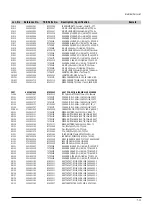
Page 50: ...Electrical Parts List 7 12 MEMO ...
Page 160: ...Operating Instructions 12 110 MEMO ...
Page 173: ...1 1 SHIBAURA 1 CHOME MINATO KU TOKYO 105 8001 JAPAN ...
Page 177: ...Block Diagrams 8 3 8 2 Digital Block Diagram ...
Page 180: ...Block Diagrams 8 6 8 5 AIC01 MSP3417 Block Diagram ...
Page 181: ...Block Diagrams 8 7 8 6 AIC02 AIC07 MC14052 Block Diagram ...
Page 182: ...Block Diagrams 8 8 8 7 AIC03 AK5357 Block Diagram ...
Page 183: ...Block Diagrams 8 9 8 8 AIC04 PCM1753 Block Diagram ...
Page 184: ...Block Diagrams 8 10 8 9 KIC01 PT6961 Block Diagram ...
Page 185: ...Block Diagrams 8 11 8 10 MIC01 78F4225 Block Diagram ...
Page 187: ...Block Diagrams 8 13 8 12 SIC01 MM1647 Block Diagram ...
Page 188: ...Block Diagrams 8 14 8 13 VIC01 74HC4051 Block Diagram ...
Page 189: ...Block Diagrams 8 15 8 14 VIC05 MM1568 Block Diagram ...
Page 190: ...Block Diagrams 8 16 MEMO ...
Page 191: ...9 Wiring Diagram 9 1 ...
Page 192: ...Wiring Diagram 9 2 MEMO ...
Page 194: ...PCB Diagrams 10 2 10 1 S M P S PCB COMPONENT SIDE ...
Page 195: ...PCB Diagrams 10 3 CONDUCTOR SIDE ...
Page 196: ...PCB Diagrams 10 4 10 2 Main PCB COMPONENT SIDE ...
Page 198: ...PCB Diagrams 10 6 10 3 Jack PCB COMPONENT SIDE ...
Page 199: ...PCB Diagrams 10 7 CONDUCTOR SIDE ...
Page 200: ...PCB Diagrams 10 8 10 4 Key PCB COMPONENT SIDE CONDUCTOR SIDE ...
Page 202: ...Schematic Diagrams 11 2 11 1 S M P S SMPS PCB ...
Page 203: ...Schematic Diagrams 11 3 11 2 Main Main PCB ...
Page 204: ...Schematic Diagrams 11 4 11 3 Audio Jack PCB ...
Page 205: ...Schematic Diagrams 11 5 11 4 Video Jack PCB ...
Page 206: ...Schematic Diagrams 11 6 11 5 AV switch Scart Jack PCB ...
Page 207: ...Schematic Diagrams 11 7 11 6 Tuner Front in Connection Jack PCB ...
Page 208: ...Schematic Diagrams 11 8 11 7 Micom Jack PCB ...
Page 209: ...Schematic Diagrams 11 9 11 8 Key Key PCB ...
Page 210: ...Schematic Diagrams 11 10 MEMO ...


