


Operating Instructions
12-95
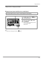
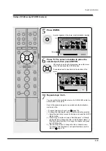
Other editing functions (Continued)
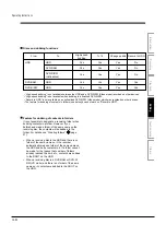
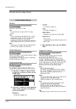
Discs and editing functions
Available editing functions may differ depending on the disc,
*1
Most suitable.
*2
You can create chapters in DVD-R/RW (Video mode) only while recording.
*3
There is a limit in the number of times DVD-R (VR mode) can be edited.
*4
Unfinalized DVD-R/RW only. (Finalized DVD-R/RW cannot be edited.)
Yes
*2
No
No
No
No
Yes
Yes
Yes
Yes
Yes
Dividing into chapter
Deleting titles or chapter
Merging chapters
Combining tltles (Original)
Editing a Playlist
Yes
*2
No
No
No
No
Yes
*1
Yes
*1
Yes
*1
Yes
*1
Yes
*1
Yes
*1
Yes
*1
Yes
*1
Yes
*1
Yes
*1
Yes
*1
Yes
*1
Yes
*1
Yes
*1
Yes
*1
Video mode
VR mode
*3
Video mode
VR mode
DVD-RW
*4
DVD-R
*4
DVD-RAM
HDD
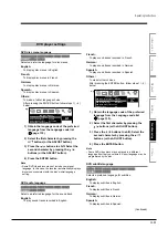
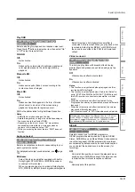
On editing of DVD-R (VR mode)
You can create chapters and make a Playlist using
recorded contents in DVD-R (VR mode), as well as
DVD-RAM or DVD-RW (VR mode). However, DVD-R
(VR mode), different from DVD-RAM or DVD-RW (VR
mode), has a limit in the number of times it can be
edited, depending on the remaining disc space or the
number of times of loading.
Additionally, DVD-R (VR mode) cannot restore the
disc space even after recorded content is deleted.
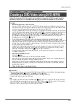
Area for recorded
titles
Area where editing
information (dividing
chapter, making
Playlist, deleting, etc.)
are saved
Each time it is edited,
the recorder writes over
the old one to save.
Area for recorded
titles
Area where editing
information (dividing
chapter, making
Playlist, deleting, etc.)
are saved
Each time it is edited,
the recorder writes the
information here adding
to the old one.
DVD-RAM, DVD-RW
DVD-R
Number of times of DVD-R (VR mode) editing
The number of times of DVD-R (VR mode) depends
on the remaining disc space. If the disc has little
space, a message appears when it is loaded, and tells
you that there are only a few times of editing left.
The number is consumed each time of creating
chapters or flashing of “Loading” icon.
Disc finalizing is available even on a disc can no
longer be edited.
Finalizing of DVD-R, different from on DVD-RW,
cannot be cancelled once executed even if there is
remaining space in the disc,
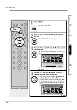
Summary of Contents for RD-XS24SB
Page 10: ...Product Specification 2 4 MEMO ...
Page 12: ...3 2 Software Update MEMO ...
Page 20: ...4 8 Disassembly and Reaasembly MEMO ...
Page 34: ...Troubleshooting 5 14 MEMO ...
Page 35: ...6 1 6 Exploded View and Parts List 6 1 Cabinet Assembly Page 6 2 ...
Page 38: ...Exploded Views and Parts List 6 4 MEMO ...
Page 50: ...Electrical Parts List 7 12 MEMO ...
Page 160: ...Operating Instructions 12 110 MEMO ...
Page 173: ...1 1 SHIBAURA 1 CHOME MINATO KU TOKYO 105 8001 JAPAN ...
Page 177: ...Block Diagrams 8 3 8 2 Digital Block Diagram ...
Page 180: ...Block Diagrams 8 6 8 5 AIC01 MSP3417 Block Diagram ...
Page 181: ...Block Diagrams 8 7 8 6 AIC02 AIC07 MC14052 Block Diagram ...
Page 182: ...Block Diagrams 8 8 8 7 AIC03 AK5357 Block Diagram ...
Page 183: ...Block Diagrams 8 9 8 8 AIC04 PCM1753 Block Diagram ...
Page 184: ...Block Diagrams 8 10 8 9 KIC01 PT6961 Block Diagram ...
Page 185: ...Block Diagrams 8 11 8 10 MIC01 78F4225 Block Diagram ...
Page 187: ...Block Diagrams 8 13 8 12 SIC01 MM1647 Block Diagram ...
Page 188: ...Block Diagrams 8 14 8 13 VIC01 74HC4051 Block Diagram ...
Page 189: ...Block Diagrams 8 15 8 14 VIC05 MM1568 Block Diagram ...
Page 190: ...Block Diagrams 8 16 MEMO ...
Page 191: ...9 Wiring Diagram 9 1 ...
Page 192: ...Wiring Diagram 9 2 MEMO ...
Page 194: ...PCB Diagrams 10 2 10 1 S M P S PCB COMPONENT SIDE ...
Page 195: ...PCB Diagrams 10 3 CONDUCTOR SIDE ...
Page 196: ...PCB Diagrams 10 4 10 2 Main PCB COMPONENT SIDE ...
Page 198: ...PCB Diagrams 10 6 10 3 Jack PCB COMPONENT SIDE ...
Page 199: ...PCB Diagrams 10 7 CONDUCTOR SIDE ...
Page 200: ...PCB Diagrams 10 8 10 4 Key PCB COMPONENT SIDE CONDUCTOR SIDE ...
Page 202: ...Schematic Diagrams 11 2 11 1 S M P S SMPS PCB ...
Page 203: ...Schematic Diagrams 11 3 11 2 Main Main PCB ...
Page 204: ...Schematic Diagrams 11 4 11 3 Audio Jack PCB ...
Page 205: ...Schematic Diagrams 11 5 11 4 Video Jack PCB ...
Page 206: ...Schematic Diagrams 11 6 11 5 AV switch Scart Jack PCB ...
Page 207: ...Schematic Diagrams 11 7 11 6 Tuner Front in Connection Jack PCB ...
Page 208: ...Schematic Diagrams 11 8 11 7 Micom Jack PCB ...
Page 209: ...Schematic Diagrams 11 9 11 8 Key Key PCB ...
Page 210: ...Schematic Diagrams 11 10 MEMO ...


