background image

Contents Error Display

*

When fixations of the errors were overlapped, the latest error is displayed.

NO

ltem

Check code

[Wired remote 

controller]

LED display

D800

(Yellow)

D801

(Yellow)

D802

(Yellow)

D803

(Yellow)

D804

(Yellow)

D805

(Green)

1

Discharge temp. sensor (TD) error

F04

۔

ە

ە

ە

ە

ۑ

2

Heat exchanger temp. sensor (TE) error

F06

ە

۔

ە

ە

ە

ۑ

4

Outside air temp. sensor (TO) error

F08

ە

ە

۔

ە

ە

ۑ

5

Suction temp. sensor (TS) error

F12

۔

ە

۔

ە

ە

ۑ

6

Heat sink temp. sensor (TH) error

F13

ە

۔

۔

ە

ە

ۑ

7

Miss-mounting of outdoor temp. sensor 
(TE, TS)

F15

۔

۔

۔

ە

ە

ۑ

8

EEPROM error

F31

ە

۔

ە

۔

ە

ۑ

9

Compressor break down

H01

۔

۔

ە

۔

ە

ۑ

1

0

Compressor lock

H02

ە

ە

۔

۔

ە

ۑ

1

1

Current detection circuit error

H03

۔

ە

۔

۔

ە

ۑ

1

2

Case thermostat operation

H04

ە

۔

۔

۔

ە

ۑ

1

3

Unset model type of P.C.board

L10

ە

ە

ە

ە

۔

ۑ

1

4

Communication error between MCUs

L29

۔

ە

ە

ە

۔

ۑ

1

5

Discharge temp. error

P03

ە

۔

ە

ە

۔

ۑ

1

6

High pressure SW system error

P04

۔

۔

ە

ە

۔

ۑ

1

7

 Power supply voltage error

P05


ە

۔

ە

۔

ۑ

1

8

Heat sink overheat error

P07

ە

۔

۔

ە

۔

ۑ

19

Gas leak detection

P15

۔

۔

۔

ە

۔

ۑ

20

High pressure protective operation

P20

۔

ە

ە

۔

۔

ۑ

21

Fan system error

P22

ە

۔

ە

۔

۔

ۑ

22

Short-circuit of compressor drive element

P25

۔

۔

ە

۔

۔

ۑ

23

Position detection circuit error

P29

ە

ە

۔

۔

۔

ۑ

2

4

Compressor IPDU or other (not specially 
identified)

۔

ە

۔

۔

۔

ۑ

2

5

Power supply error

ە

ە

ە

ە

ە

ە

ۑ

: ON   

ە

 : OFF   

۔

: Rapid flash (5 times /sec.)

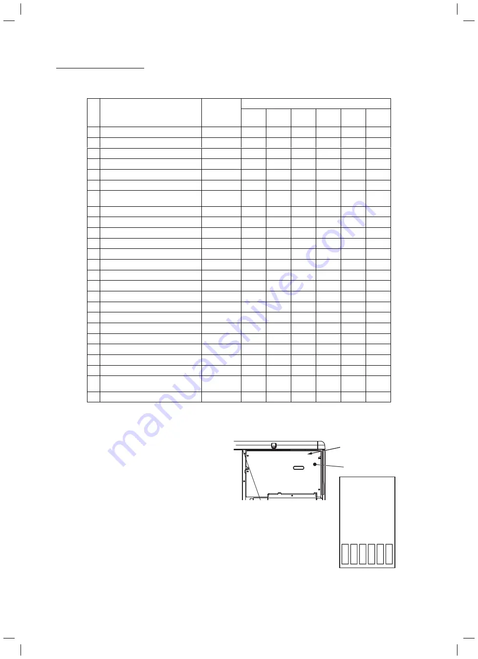
D800

D801

D802

D803

D804

D805

(Yellow)

(Yellow)

(Yellow)

(Yellow)

(Yellow)

(Gr

een)

Inspection window 
through which to check 
the LED displays

Electric parts  cover

*

The LEDs are located at the top right of the P.C.

board of the outdoor unit as shown in the figure
on the right.

ە

3

Heat exchanger temp. sensor (TL) error

F0

7

۔

۔

ە

ە

ە

ۑ

- 48 -

FILE NO. SVM-17005

Summary of Contents for RAV-SM1104AT8JP-E

Page 1: ...SERVICE MANUAL OUTDOOR UNIT DIGITAL INVERTER RAV SM1104AT8P E TR RAV SM1404AT8P E TR RAV SM1104AT8JP E RAV SM1404AT8JP E AIR CONDITIONER SPLIT TYPE Revised no March 2017 FILE NO SVM 17005 2 ...

Page 2: ...A 23 6 1 Safety During Installation Servicing 23 6 2 Refrigerant Piping Installation 23 6 3 Tools 27 6 4 Recharging of Refrigerant 27 6 5 Brazing of Pipes 28 6 6 Instructions for Re use Piping of R22 or R407C 30 6 7 Replenishing refrigerant 33 7 OUTDOOR CONTROL CIRCUIT 34 7 1 Outdoor unit control 34 7 2 Outline of Main controls 36 8 TROUBLESHOOTING 41 8 1 Summary of Troubleshooting 41 8 2 Troubles...

Page 3: ...thus thoroughly acquainted with the knowledge related to this work s The qualified installer who is allowed to work at heights has been trained in matters relating to working at heights with the air conditioners made by Toshiba Carrier Corporation or alternatively he or she has been instructed in such matters by an individual or individuals who have been trained and is thus thoroughly acquainted w...

Page 4: ...lowing contents Indications Illustrated marks and keep them Explanation of indications Indication DANGER WARNING CAUTION Explanation Indicates contents assumed that an imminent danger causing a death or serious injury of the repair engineers and the third parties when an incorrect work has been executed Indicates possibilities assumed that a danger causing a death or serious injury of the repair e...

Page 5: ...when removing this panel CAUTION Do not touch the aluminum fins of the unit Doing so may result in injury CAUTION BURST HAZARD Open the service valves before the operation otherwise there might be the burst Description WARNING ELECTRICAL SHOCK HAZARD Disconnect all remote electric power supplies before servicing WARNING Moving parts Do not operate unit with grille removed Stop the unit before the ...

Page 6: ...ocedure refer to the Service Manual You may receive an electric shock if the voltage stored in the capacitors has not been sufficiently discharged Place a Work in progress sign near the circuit breaker while the installation maintenance repair or removal work is being carried out There is a danger of electric shocks if the circuit breaker is set to ON by mistake When checking the electric parts re...

Page 7: ... cycle When using a gas stove etc be sure to put out fire before work otherwise the oil mixed with refrigerant gas may catch fire 2 Do not use a welder in the closed room When using it without ventilation carbon monoxide poisoning may be caused 3 Do not bring inflammables close to the refrigerant cycle otherwise fire of the welder may catch the inflammables WARNING General Check earth wires Prohib...

Page 8: ...r repair work surely assemble the disassembled parts and connect and lead the removed wires as before Perform the work so that the cabinet or panel does not catch the inner wires If incorrect assembly or incorrect wire connection was done a disaster such as a leak or fire is caused at user s side After the work has finished be sure to use an insulation tester set 500V Megger to check the resistanc...

Page 9: ...cked in raising the pressure inside the refrigeration cycle to an abnormally high level and possibly resulting in reputing injury etc When the service panel of the outdoor unit is to be opened in order for the compressor or the area around this part to be repaired immediately after the air conditioner has been shut down set the circuit breaker to the OFF position and then wait at least 10 minutes ...

Page 10: ...cribed below Generic Denomination Model type Commercial name Digital Inverter Series Air Conditioner Complies with the provisions of the Machinery Directive Directive 2006 42 EC and the regulations transposing into national law Complies with the provisions of the following harmonized standard EN 378 2 2008 A2 2012 Note This declaration becomes invalid if technical or operational modifications are ...

Page 11: ...Sound power level dBA Weight kg Cooling Heating RAV SM1104AT8P E 71 69 RAV SM1104AT8JP E 71 69 RAV SM1404AT8P E 71 69 RAV SM1404AT8JP E 71 69 RAV SM1104AT8P TR 71 69 RAV SM1404AT8P TR 71 69 Under 70 dBA 11 FILE NO SVM 17005 ...

Page 12: ...ecause pipes are affected by impurities such as water oxide scales oil etc Use the clean pipes Be sure to brazing with flowing nitrogen gas Never use gas other than nitrogen gas 4 For the earth protection use a vacuum pump for air purge 5 R410A refrigerant is azeotropic mixture type refrigerant Therefore use liquid type to charge the refrigerant If using gas for charging composition of the refrige...

Page 13: ...uum pump Use vacuum pump by attaching vacuum pump adapter 7 Screwdriver h c n e r w y e k n o M r o r e n n a p S 8 h c n e r w e u q r o T 2 l l i r d e r o c e l o H 9 r e t t u c e p i P 3 m m 4 e d i s e t i s o p p O h c n e r w n o g a x e H 0 1 r e m a e R 4 e r u s a e m e p a T 1 1 r e d n e b e p i P 5 w a s l a t e M 2 1 l a i v l e v e L 6 Also prepare the following equipments for othe...

Page 14: ...50m Height difference Outdoor lower m 30 30 Outdoor higher m 30 30 Outer dimension Height mm 890 890 Width mm 900 900 Depth mm 320 320 Appearance Silky shade Muncel 1Y8 5 0 5 Total weight kg 69 69 Heat exchanger Finned tube Fan unit Fan Propeller fan Standard air flow high m3 min 68 70 Motor W 100 100 Connecting pipe Gas side mm 15 9 15 9 Liquid side mm 9 5 9 5 Sound pressure level Cooling Heating...

Page 15: ...eed RPS SM110 SM140 SM110 SM140 s Capacity variation ratio according to temperature 1 2 Operation Characteristic Curve RAV SM1104AT P SM1404AT P Cooling Heating 0 10 20 30 40 50 60 70 80 90 100 110 120 14 12 10 8 6 4 6 8 10 4 2 0 2 Outdoor temp C Capacity ratio 50 55 60 65 70 75 80 85 90 95 100 105 110 30 31 32 33 34 35 36 37 38 39 40 41 42 43 44 45 46 SM140 SM110 15 FILE NO SVM 17005 ...

Page 16: ...2 1 RAV SM1104AT8 P SM1404AT8 P 2 CONSTRUCTION VIEWS EXTERNAL VIEWS 16 FILE NO SVM 17005 ...

Page 17: ...ous Twin Inner diameter Ø C Inner diameter Ø D Inner diameter Ø D A B Model RBC TWP30E2 Liquid side Gas side TWP50E2 Liquid side Gas side A B C D 36 14 Ø9 5 Ø6 4 43 23 Ø15 9 Ø12 7 34 14 Ø9 5 Ø9 5 44 21 Ø15 9 Ø15 9 17 FILE NO SVM 17005 ...

Page 18: ...ch pipe Air heat exchanger Heating Cooling Indoor unit Refrigerant pipe at liquid side Outer dia ØB Refrigerant pipe at gas side Outer dia ØA Distributor Strainer incorporated Strainer Heating Cooling TCJ sensor TC sensor Air heat exchanger To outdoor unit To outdoor unit s Single type Combination of 1 indoor unit and 1 outdoor unit s Twin type Combination of 2 indoor units and 1 outdoor unit Indo...

Page 19: ...nsor Distributor 4 way valve STF H0218 Ø25 L180 Ø25 L210 Rotary compressor RA330A2T 20M Accumulator 1800cc Heat exchanger Ø8 2 rows 40 steps FP1 3 flat fin R410A 2 8kg Cooling Heating Muffler PMV Pulse Motor Valve CAM BD25TCTH 1 P Pressure switch 3 2 Outdoor Unit RAV SM1104AT8 P SM1404AT8 P 19 FILE NO SVM 17005 ...

Page 20: ...5 17 80 HIGH 15 15 RAV SM1404AT8 P Pressure Pipe surface temperature C Comp Hz Fan Temp MPa kg cm2 G Pd Ps Pd Ps TD TS TC TE In Out Cooling Standard 3 24 0 73 34 4 8 7 90 10 8 40 77 HIGH 27 19 35 Overload 3 72 1 10 37 2 10 9 86 16 18 54 53 HIGH 32 24 46 Low load 2 05 0 83 20 9 8 5 41 10 8 4 20 LOW 18 15 5 15 Heating Standard 2 57 0 60 28 4 6 4 69 1 40 1 72 HIGH 20 7 6 Overload 3 38 0 99 30 6 11 4 ...

Page 21: ...R L2 Y L3 B N TB1 TB2 BACK FRONT Parts Layout P C board Connector Terminal Terminal block Protective earth Field wiring YEL YELLOW BRW BROWN WHI WHITE GRN GREEN GRY GRAY RED RED BLU BLUE BLK BLACK Color Indication Terminal block to indoor unit Terminal block power supply Air temp sensor Heat exchange temp sensor Pipe temp sensor Discharge Pipe temp sensor Suction Rush current protect resistor Puls...

Page 22: ...harge temp sensor TD sensor 50 kΩ at 25 C 11 Suction temp sensor TS sensor 10 kΩ at 25 C 12 Heat exchanger sensor TE sensor 10 kΩ at 25 C 14 Fuse Mounted on P C board MCC 1626 50T 100H T10A 250V 15 Fuse Mounted on P C board MCC 1626 50 P 063HF GF001 C4 T6 3A 250V 16 Fuse Mounted on P C board MCC 1626 SCT 3 15A 3 15A 250V 17 Fuse Mounted on P C board MCC 1627 50 P 063HF GF001 C4 T6 3A 250V 18 Fuse ...

Page 23: ...upture or personal injury may be caused 5 After completion of installation work check to make sure that there is no refrigeration gas leakage If the refrigerant gas leaks into the room coming into contact with fire in the fan driven heater space heater etc a poisonous gas may occur 6 When an air conditioning system charged with a large volume of refrigerant is installed in a small room it is neces...

Page 24: ...that water or dust does not enter the pipe interior that no other oil other than lubricating oils used in the installed air conditioner is used and that refrigerant does not leak When using lubricating oils in the piping processing use such lubricating oils whose water content has been removed When stored be sure to seal the container with an airtight cap or any other cover 1 Flare Processing Proc...

Page 25: ...to 0 5 Conventional flare tool R410A Clutch type Wing nut type 1 0 to 1 5 1 5 to 2 0 1 0 to 1 5 1 5 to 2 0 1 0 to 1 5 2 0 to 2 5 1 0 to 1 5 2 0 to 2 5 Conventional flare tool R22 Clutch type Wing nut type 0 5 to 1 0 1 0 to 1 5 0 5 to 1 0 1 0 to 1 5 0 5 to 1 0 1 5 to 2 0 0 5 to 1 0 1 5 to 2 0 Table 6 2 4 Flare and flare nut dimensions for R410A Table 6 2 5 Flare and flare nut dimensions for R22 Nom...

Page 26: ...ay crack and may be made non removable When choosing the tightening torque comply with values designated by manufacturers Table 6 2 6 shows reference values NOTE When applying oil to the flare surface be sure to use oil designated by the manufacturer If any other oil is used the lubricating oils may deteriorate and cause the compressor to burn out Table 6 2 6 Tightening torque of flare for R410A R...

Page 27: ... in the fully closed position and turn off the vacuum pump s power switch Keep the status as it is for 1 to 2 minutes and ensure that the compound gauge s pointer does not return Set the refrigerant cylinder to the electronic balance connect the connecting hose to the cylinder and the connecting port of the electronic balance and charge liquid refrigerant 1 Never charge refrigerant exceeding the s...

Page 28: ...loy mainly composed of silver and copper It is used to join iron copper or copper alloy and is relatively expensive though it excels in solder ability 2 Phosphor bronze brazing filler Phosphor bronze brazing filler is generally used to join copper or copper alloy 3 Low temperature brazing filler Low temperature brazing filler is generally called solder and is an alloy of tin and lead Since it is w...

Page 29: ... use a flux which does not contain chlorine 3 When adding water to the flux use water which does not contain chlorine e g distilled water or ion exchange water 4 Remove the flux after brazing 6 5 3 Brazing As brazing work requires sophisticated techniques experiences based upon a theoretical knowledge it must be performed by a person qualified In order to prevent the oxide film from occurring in t...

Page 30: ...se of trouble will occur 8 Installation and removal of the air conditioner are repeated with temporary installation by lease and etc 9 In case that type of the refrigerator oil of the existing air conditioner is other than the following oil Mineral oil Suniso Freol S MS Synthetic oil alkyl benzene HAB Barrel freeze ester series PVE only of ether series s Winding insulation of the compressor may be...

Page 31: ...ns inside of the pipe Note In case of twin also be sure to flash the branching pipe Connect the indoor outdoor units to the existing pipe s Use a flare nut attached to the main unit for the indoor outdoor units Do not use the flare nut of the existing pipe s Re machine the flare machining size to size for R410A Nitrogen gas pressure 0 5 Mpa If there is discharge of remains it is judged that there ...

Page 32: ...indoor unit or outdoor unit for a long period s The pipe has been connected to an outdoor unit that does not use refrigerant R22 R410A or R407C s The existing pipe must have a wall thickness equal to or larger than the following thickness s Never use any pipe with a wall thickness less than these thicknesses due to insufficient pressure capacity Reference outside diameter mm Ø9 5 Ø15 9 Ø19 1 Wall ...

Page 33: ...ecover the refrigerant and replenish the refrigerant Restrictions for the amount of additional charging a The amount of refrigerant additionally charged shall not exceed 10 of that specified If the situation is not solved with such amount recover the refrigerant completely and charge the specified amount b In case of slow leakage upon installation and the pipe connection length of not over 15m fur...

Page 34: ...lect J800 J806 LED Display D800 805 Case thermo CN500 High pressure SW CN501 Relay output CN502 PMV coil output CN701 Sensor input TL CN604 TD CN603 TO CN602 TE CN601 TS CN600 Fuse for Indoor Unit F02 Connection with indoor unit CN03 Power supply CN04 Power supply CN05 Fan output CN300 Coil value 4 way output CN700 34 FILE NO SVM 17005 ...

Page 35: ...t W phase CN202 Compressor output V phase CN201 Compressor output U phase CN200 Reactor connecting terminal CN08 UART Communication CN852 Power supply L2 P02 Power supply L3 P03 Power supply L1 P01 Relay input CN11 Reactor connecting terminal CN07 Earth P05 Neutral P04 35 FILE NO SVM 17005 ...

Page 36: ...ssive shortening of the compressor life In a case of trouble on the compressor be sure to check there is no error in the resistance value an the refrigerating cycle of each sensor after repair and then start the operation 2 Discharge temperature release control 1 When the discharge temperature did not fall or the discharge temperature rapidly went up by PMV control this control lowers the compress...

Page 37: ...ntrolled by TL sensor TO sensor and compressor frequency An outdoor fan is controlled at 1 tap interval of DC fan control 2 At the start time the fan is fixed for 60 seconds only with the maximum fan tap corresponded to the zone in the following table but it is controlled with TL sensor temperature after then 1 tap 20 sec Up to the maximum rotational frequency of each zone Rotational frequency hol...

Page 38: ...p range SM110 SM140 20 4 Hz or lower 20 4Hz to 45 0Hz 45 0Hz or higher Max Max Max 10 C TO W7 W8 W9 5 C TO 10 C W9 WB WE 3 C TO 5 C WE WE WE 10 C TO 3 C WE WE WE TO 10 C WE WE WE TO error WE WE WE 5 Coil heating control 1 This control function heats the compressor by turning on the stopped compressor instead of a case heater It purposes to prevent stagnation of the refrigerant inside of the compre...

Page 39: ...eck code list 9 High pressure release control 1 The operation frequency is controlled to restrain abnormal rising of high pressure by TL sensor in cooling operation and TC sensor in heating operation 2 When TL sensor in cooling operation or TC sensor in heating operation detects abnormal temperature of the stop zone stop the compressor and the error count becomes 1 3 When the compressor stopped wi...

Page 40: ...TEO TE 3 C continued for 20 seconds When status of TEO TE ToO TO 2 C continued for 20 seconds B zone When status of TEO TE 2 C continued for 20 seconds C zone When status of SM110 140 TE 18 C continued for 20 seconds D zone When compressor operation status with SM110 140 TE 2 C are added by d times 11 High pressure switch 1 When the high pressure switch operates the operation of the compressor is ...

Page 41: ...ot be performed from remote controller Is not the control operation performed from outside remote side Is not automatic address being set up When the power is turned on at the first time or when indoor unit address setting is changed the operation cannot be performed for maximum approx 5 minutes after power ON Is not being carried out a test run by operation of the indoor controller b Did you retu...

Page 42: ...address being set up Is not being carried out a test run by operation of the indoor controller b Did you return the cabling to the initial positions c Are connecting cables between indoor unit and receiving unit correct 2 Troubleshooting procedure When the power is turned on at the first time or when indoor unit address setting is changed the operation cannot be performed for maximum approx 5 minu...

Page 43: ... Duplicated header units of remote controller Setup error E09 E10 Communication error between CPUs on indoor unit P C board E18 Wire connection error between indoor units Indoor power OFF Communication stop between indoor master and follower or between main and sub indoor twin Operation Timer Ready Flash E04 Miswiring between indoor unit and outdoor unit or connection error Communication stop betw...

Page 44: ...rcuit error Outdoor P C board error H04 Case thermostat operation Outdoor compressor overheat error Outdoor unit connection error Operation Timer Ready Simultaneous flash L03 Duplicated header indoor units AUTO address If group construction and address are not normal power supply turned on automatically goes to address setup mode L07 There is indoor unit of group connection in individual indoor un...

Page 45: ...tected 17 H03 Outdoor unit Current detection circuit error Outdoor Current detection circuit error 44 H04 Outdoor unit case thermostat worked Outdoor Case thermostat worked 88 L10 SIM Outdoor unit Unset model type of service P C board Outdoor When outdoor service P C board was used model type select jumper setting was inappropriate 1C L29 SIM Outdoor unit Communication error between MCUs Outdoor C...

Page 46: ...cted 1 Check outdoor P C board L10 Unset jumper of service P C board Stop Displayed when error is detected 1 Outdoor service P C board Check model type setting jumper wire L29 Communication error between MCUs of outdoor unit Stop Displayed when error is detected 1 Check outdoor P C board 2 Check connection between outdoor P C boards H01 Compressor break down Although operation has started operatio...

Page 47: ...radiator grease 2 Check heat sink blast path P15 Gas leak detection Discharge temp sensor TD Suction temp sensor TS detected temperature over specified temp Stop Displayed when error is detected 1 Check gas leak recharge 2 Check full open of service valve 3 Check PMV Pulse Motor Valve 4 Check broken pipe 5 Check discharge temp sensor TD suction temp sensor TS P20 High pressure protective operation...

Page 48: ...l type of P C board L10 ە ە ە ە ۑ 14 Communication error between MCUs L29 ە ە ە ۑ 15 Discharge temp error P03 ە ە ە ۑ 16 High pressure SW system error P04 ە ە ۑ 17 Power supply voltage error P05 ە ە ۑ 18 Heat sink overheat error P07 ە ە ۑ 19 Gas leak detection P15 ە ۑ 20 High pressure protective operation P20 ە ە ۑ 21 Fan system error P22 ە ە ۑ 22 Short circuit of compressor drive element P25 ە ۑ ...

Page 49: ... when the same error occurred continuously by multiple times while LED of the outdoor P C board displays even an error which occurred once Therefore the display on the wired remote controller may differ from that of LED LED display on outdoor P C board Display of error which is generating When even one of D800 to D804 rapid flashing it indicates that an error occurred ە D800 Yellow ە ە D801 Yellow...

Page 50: ... blocks 1 2 3 correct YES YES YES NO NO NO F04 Discharge temp sensor TD error Is connection of CN603 correct Is resistance value of TD sensor correct Correct connector Sensor error Replace Check outdoor P C board Defect Replace YES NO F06 Heat exchanger temp sensor TE error Is connection of CN601 correct Is resistance value of TE sensor correct Correct connector Sensor error Replace Check outdoor ...

Page 51: ... board Defect Replace Is connection of CN600 correct Is resistance value of TS sensor correct YES NO F13 Heat sink temp sensor TH error Check outdoor P C board MCC 1627 Defect Replace F15 Miss mounting of heat exchanger sensor TE TS Check outdoor P C board Defect Replace Correct connector Sensor error Replace Correct connector Sensor error Replace Correct sensor mounting Is mounting status of TE a...

Page 52: ... correct Compressor lead P C board side Compressor side Reactor lead Power supply lead YES YES YES NO NO NO H02 Compressor lock Check wire connection and correct it Correct power supply line Is compressor under correct conditions Is there refrigerant stagnation Does PMV correctly operate Is power supply voltage correct AC342 to 457V Is wire connection correct Compressor lead P C board side Compres...

Page 53: ...nection and case thermostat correct Short each pins of CN500 Can compressor operate YES YES NO YES YES NO NO YES NO NO L10 Unset model type Only when service P C board is used Cut jumper line according to the explanation sheet packaged with the service P C board L29 Communication error between MCUs Check outdoor P C board Defect Replace P03 Discharge temp error Check outdoor P C board Defect Repla...

Page 54: ... high pressure switch operate Are parts of high pressure switch correct Reset the power supply and then make a test run Is there any element which blocks heat exchanger of the outdoor unit Clogging of heat exchanger Short circuit Parts check Defective Replace Elimination of blocking element Check outdoor PC board Defective Replace Wiring check Correct Open service valve fully Repair defective posi...

Page 55: ...ing block air flow from the fan Apply radiation grease to objective parts Retightening of screws NO NO YES YES Is the power device on P C board screwed without looseness Q200 of MCC 1627 Are radiation grease properly applied Q200 of MCC 1627 P15 Gas leak detection Check outdoor P C board Defect Replace Repair defective position Replace defective part Repair defective position Recharge refrigerant ...

Page 56: ...ed Is there any defect such as loosening of nut in the outdoor fan Does the outdoor fan perform abnormal operation Is resistance value of TE sensor correct Replace TE sensor Check the same items as P22 error Check overcharge of refrigerant clogging of cycle broken pipe abnormal overload etc Defect Correct defect Eliminate interfering element Is there anything which interfere heat exchange of outdo...

Page 57: ...t sink Does something block air flow from the fan Rotate shaft of the fan motor by hands during power OFF Can it rotate smoothly Is coil resistance of fan motor correct Between red and white lead wire 12 to 20Ω Between white and black lead wire 12 to 20Ω Between black and red lead wire 12 to 20Ω NO YES NO NO YES YES YES YES Check outdoor P C Board Defect Replace Check wiring construction Ask repai...

Page 58: ... compressor Rear short etc Defect Replace Are connections of compressor lead and reactor correct Check referring to the Wiring diagram NO YES P29 Position detection circuit error Check outdoor P C board Defect Replace No code Other error Compressor disorder due to sudden change of load etc Although the display of outdoor LED outputs the unit automatically restarts and error is not determined LED d...

Page 59: ...Minimum value Standard value Maximum value 0 150 5 161 3 172 7 10 92 76 99 05 105 6 20 58 61 62 36 66 26 25 47 01 49 93 52 97 30 37 93 40 22 42 59 40 25 12 26 55 28 03 50 17 00 17 92 18 86 60 11 74 12 34 12 95 70 8 269 8 668 9 074 80 5 925 6 195 6 470 90 4 321 4 507 4 696 100 3 205 3 336 3 468 Resistance kΩ 50ºC or lower Resistance kΩ 50ºC or higher 0 0 50 100 150 200 0 5 10 15 20 10 20 30 40 50 6...

Page 60: ...lack Red Under 20 C Red White Black 2 Outdoor fan motor Model WDF 340 A100 1 Measure the resistance value of each winding by using the tester Position Resistance value Red White 17 3 1 7 Ω White Black Black Red Under 20 C Red White Black 3 4 way valve coil Cooling heating switching Model STF H Measure the resistance value of each winding by using the tester Resistance value 7 1 0 36 Ω Under 20 C C...

Page 61: ...emote controller 1 1 OUT IN 2 1 Master OUT IN 3 1 OUT IN 4 1 OUT IN 7 1 Max 8 units 1 Display range on remote controller The setup range Operation mode Air volume select Setup temp of the indoor unit which was set to the master unit is reflected on the remote controller 2 Address setup Turn on power of the indoor unit to be controlled in a group within 3 minutes after setting of automatic address ...

Page 62: ...vailable Approx 50 seconds after power ON Regular communication between indoor units Every 30 seconds Master Follower Regular communication on the identical pipe every 30 seconds Twin Master Follower When the above status changes immediately communicates Repetition The unit without power feed waits entirely Waiting status is released by system start Reboot when power is fed on the way 3 minutes el...

Page 63: ...tioner 2 To set the air conditioner to test run mode hold down the Temporary button for more than 10 seconds Then you will hear a Pi sound and the light green light green and light orange lamps will blink quickly to indicate that the air conditioner has gone into a test run mode 3 Wait for one minute to elapse and then close the valve of liquid side 4 It is recommended to attach a pressure gauge a...

Page 64: ...p plate Hexagonal screw Ø4 10 5 pcs In this time insert the fin guard of rear side between the top plate and the heat exchanger Rear side 2 Connect the power supply wire and the indoor outdoor connecting wire to the terminal and fix it with cord clamp CAUTION Using bundling band on the market be sure to fix the power wire and indoor outdoor connecting wire along the crossover pipe so that they do ...

Page 65: ...rews of the discharge port cabinet and the fin guard Hexagonal screw Ø4 10 2 pcs Remarks Side cabinet 3 1 Detachment 1 Carry out work of 1 of 1 2 Remove screws which fix the inverter assembly and the side cabinet ST1T Ø4 8 2 pcs 3 Remove screws of the side cabinet and the valve fixing plate ST1T Ø4 8 2 pcs 4 Remove screws of the side cabinet and the pipe panel Rear Hexagonal screw Ø4 10 2 pcs 5 Re...

Page 66: ...se thermo 2P Blue CN501 High pressure switch 2P Green CN502 Relay output 2P White CN600 TS sensor 3P White tube CN601 TE sensor 2P White tube CN602 TO sensor 2P Yellow tube CN603 TD sensor 3P White tube CN604 TL sensor 2P White tube CN700 4 way coil 2P Yellow CN701 PMV coil 5P Blue CN851 UART Communication 6P Red 4 Remove the P C board from the 6 PCB Mounts 2 Attachment 1 Mount the P C board to in...

Page 67: ... fast on terminals from PTC thermistor Remove the connectors by pulling the connector body Do not pull the wire 8 Remove the P C board from the 3 PCB Mounts 9 Remove all the connectors and fast on terminals connected to the P C board Remove the connectors and fast on terminals by pulling the connector body Do not pull the wire Connectors should be removed after unlocking the housing section CN11 R...

Page 68: ...out works of 1 of 1 and 3 2 Remove the relay connector connected to the control P C board Remarks 3 Remove each reactor Truss B tight screw Ø4 6 2 pcs each 4 Attach a new reactor Reactor relay connector Connected to lead wire White at P C board side 5 Screws 68 FILE NO SVM 17005 ...

Page 69: ...cken in order not to put the fan motor lead into contact with the propeller fan Attach the fan motor lead fixing rubber to the partition plate so that projection directs to the refrigerating cycle side Be sure that the rector body does not come to contact with the fan motor lead Be sure to bind the removed bundling band with the bundling band on the market CAUTION Use the metal band of the motor b...

Page 70: ...e valve fixing plate and the accumulator Hexagonal screw Ø4 10 1 pc Cut off the bundling band for the dis charge pipe and the suction pipe and then remove each sensor and coil lead of PMV 6 Remove the soundproof plate Upper side outer winding inner winding 7 Remove terminal cover from the compressor and then remove the compressor lead and also the compressor case thermo 8 Remove TD sensor fixed to...

Page 71: ...ted so take sufficient care CAUTION Note so that the flame does not catch the 4 way valve and PMV An operation may become an error 11 Pull off the discharge pipe and the suction pipe of the refrigerating cycle upward 12 Remove the compressor bolts which fix the compressor to the bottom plate 3 pcs 13 Pull out the compressor toward you X CAUTIONX The weight of the compressor is 15kg or more so hand...

Page 72: ...V coil lead wire to the discharge pipe and the suction pipe with the bundling band via the pipe cover In this time take note that each sensor and PMV coil lead wire do not come to contact with the discharge pipe and the reactor For fixing to the discharge pipe use the black heat proof pipe cover and the bundling band for heat proof which is sold on the market As shown in the right figure mount the...

Page 73: ...pe valve and PMV of the outdoor unit Forced full opening method of PMV 4 Refrigerant charging 1 Add the quantity of refrigerant specified by the pipe length into the charge port of the valve Remarks 1 Detachment 1 Carry out works of 1 of 1 and 3 2 While pulling the coil upward and removing the spring which pinches the copper pipe remove the coil from PMV main body 2 Attachment 1 Match the spring t...

Page 74: ... 4 Cut the bundling bands that fixate high pressure switch lead line 5 Remove the connector for high pressure switch from the inverter 6 Remove the High pressure switch Cautions when assembling the high pressure switch Tighten the high pressure switch with 11 1N m Tightening work must use two spanners Inverter Cut the bundling band High pressure switch connector 9 High pressure switch Cut the bund...

Page 75: ...rt cabinet and then put on it so that the fan guard side directs downward 3 Remove the hooking claws 8 positions of the fan guard 2 Attachment 1 Push the hooking claws 8 positions with hands from the front side to fix the claws CAUTIONX Check that all the hooking claws are fixed at the specified positions Remarks Bell mouth Discharge port cabinet Fan guard Hooking claw 10 75 FILE NO SVM 17005 ...

Page 76: ...11 EXPLODED VIEWS AND PARTS LIST 11 1 RAV SM1104AT8P E SM1104AT8JP E SM1104AT8P TR RAV SM1404AT8P E SM1404AT8JP E SM1404AT8P TR 76 FILE NO SVM 17005 1 ...

Page 77: ...1 1 1 1 1 1 20 43T46380 VALVE PACKED 9 52 DIA 1 1 1 1 1 1 21 43T43492 ASM COND 1 1 1 1 1 1 23 43T47372 STRAINER 1 1 1 1 1 1 24 43T47396 STRAINER 1 1 1 1 1 1 25 43T60478 ASM SERV MOT 1 1 1 1 1 1 26 43T20352 FAN PR PB522 1 1 1 1 1 1 27 43T19372 FAN GUARD TOSHIBA 1 1 1 1 1 1 28 43T22313 BELLMOUTH 1 1 1 1 1 1 29 43T19345 FIN GUARD 1 1 1 1 1 1 30 43T71302 HANDLE 2 2 2 2 2 2 32 43T54319 BIMETAL THERMO 1...

Page 78: ...Inverter assembly RED WHI GRY RED WHI BLK GRY BRW 419 424 421 426 425 421 421 421 424 425 425 410 411 417 415 413 416 414 420 421 425 TL TS TO TD 423 422 418 78 FILE NO SVM 17005 ...

Page 79: ...NSOR 1 1 417 43T63316 HOLDER SENSOR 1 1 418 43T6V881 PC BOARD ASSY CDB MCC 1626 1 419 43T6V883 PC BOARD ASSY IPDU MCC 1627 1 1 420 43T60413 FUSE 1 1 421 43T95301 SUPPORT SPACER 5 5 422 43T60419 TERMINAL 4P 1 1 423 43T60331 TERMINAL 3P 1 1 424 43T50345 THERMISTOR PTC 1 1 425 43T95302 SPACER EDGE 4 4 426 43T60479 WIRE ASSY COMP LEAD 1 1 Location No Part No Description RAV SM1404AT8P E SM1404AT8JP E ...

Page 80: ...he refrigerant accidentally leaks out its concentration does not reach the limit and in the event of an emergency measures can be made before injury can occur In a room where the concentration may exceed the limit create an opening with adjacent rooms or install mechanical ventilation combined with a gas leak detection device The concentration is as given below Total amount of refrigerant kg Conce...

Page 81: ...TOSHIBA CARRIER THAILAND CO LTD 144 9 MOO 5 BANGKADI INDUSTRIAL PARK TIVANON ROAD TAMBOL BANGKADI AMPHUR MUANG PATHUMTHANI 12000 THAILAND ...

Reviews: