FC-22 ADJUSTMENT
1 - 82
January 2000 © TOSHIBA TEC
Note:
If the adjustment finer than that in the above table is required, perform “Fine adjustment of polygonal
motor rotation speed”.
(5)
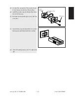
Install the lens cover and original glass, and then make a copy to confirm the reproduction ratio.
(6)
Remove the original glass and lens cover again, and then tighten the 2 screws for the lens unit to fix
its position.
(7)
Remove the 2 pins used for adjusting the lens magnification ratio.
(8)
Reinstall the damp heater unit, lens shield bracket, lens cover and original glass.
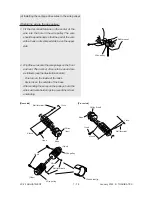
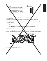
(4)
Using the marks on the scanner base as a guide, adjust the lens unit in either forward or backward
direction.
The following table shows the error in the reproduction ratio between the copies and actual rulers
compared to be measured, and the amount of adjustment of the lens unit.
Reproduction-ratio error Amount of adjustment
0.1 %
0.5 mm
0.2 %
0.9 mm
0.3 %
1.4 mm
0.4 %
1.9 mm
0.5 %
2.4 mm
0.6 %
2.9 mm
0.7 %
3.3 mm
0.8 %
3.8 mm
0.9 %
4.3 mm
1.0 %
4.8 mm
Marking
Adjustment
direction
For larger-
than-100%
ratios
For smaller-
than-100%
ratios
Exit side
Lens unit
Feed side
Summary of Contents for FC22
Page 115: ...FC 22 PREVENTIVE MAINTENANCE 2 8 January 2000 TOSHIBA TEC Front side drive system 47 20 ...
Page 121: ......
Page 235: ...January 2000 TOSHIBA TEC 5 29 FC 22 FIRMWARE UPDATING ...
Page 237: ...FC 22 SERVICE HANDBOOK 6 WIRE HARNESS CONNECTION DIAGRAMS 6 2 DC Wire Harness ...
Page 238: ...FC 22 WIREHARNESS CONNECTION DIAGRAMS 6 3 January 20000 TOSHIBA TEC ...


