January 2000 © TOSHIBA TEC
4 - 45
FC-22
TROUBLESHOOTING
4.1.19
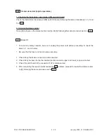
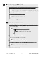
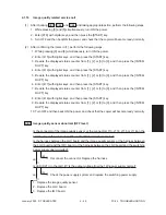
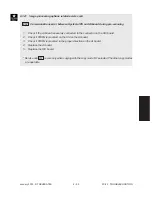
Image quality related service call
(1)
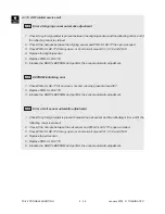
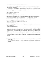
After checking CE1 , CE2 and CE4 , and taking appropriate action, perform the following steps.
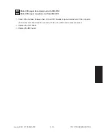
1. While pressing [0] and [5] simultaneously, turn ON the power.
2. Enter [878] with digital keys, and then press the [START] key.
3. Turn OFF and then back ON the power, and check that the copier will become ready normally.
(2)
After confirming the items in (1), perform the following steps.
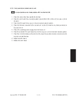
1. While pressing [0] and [8] simultaneously, turn ON the power.
2. Enter [415] with digital keys, and then press the [START] key.
3. Rewrite the displayed status counter from [1], [2] or [3] to [0], and then press the [INTER-
RUPT] key.
4. Enter [416] with digital keys, and then press the [START] key.
5. Rewrite the displayed status counter from [1], [2] or [3] to [0], and then press the [INTER-
RUPT] key.
6. Enter [417] with digital keys, and then press the [START] key.
7. Rewrite the displayed status counter from [1], [2] or [3] to [0], and then press the [INTER-
RUPT] key.
8. Enter [418] with digital keys, and then press the [START] key.
9. Rewrite the displayed status counter from [1], [2] or [3] to [0], and then press the [INTER-
RUPT] key.
10. Turn OFF and then back ON the power, and check that the copier will become ready normally.
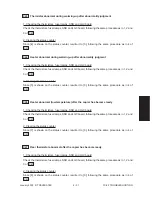
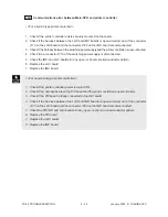
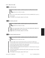
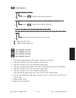
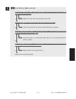
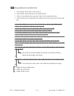
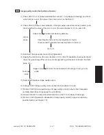
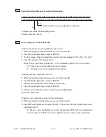
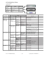
CE1 Image quality sensor abnormal (OFF level)
Is the connector of the image quality sensor, or the connector J113, J114, J115 or J118 on the
LGC board, or the connector J168 on the IMC board disconnected?
Is the harness between the LGC board and the image quality sensor, or the harness between
the LGC board and the IMC board, or the harness between the LGC board and the switching
power supply open-circuited?
Reconnect the connector. Replace the harness.
Is LED (D21) on the LGC lit? Is the output voltage from the 12V-power supply normal?
Check the power supply system and replace the switching power supply.
1. Replace the image quality sensor.
2. Replace the LGC board.
3. Replace the IMC board.
NO
▼
YES
▼
NO
▼
YES
▼
Summary of Contents for FC22
Page 115: ...FC 22 PREVENTIVE MAINTENANCE 2 8 January 2000 TOSHIBA TEC Front side drive system 47 20 ...
Page 121: ......
Page 235: ...January 2000 TOSHIBA TEC 5 29 FC 22 FIRMWARE UPDATING ...
Page 237: ...FC 22 SERVICE HANDBOOK 6 WIRE HARNESS CONNECTION DIAGRAMS 6 2 DC Wire Harness ...
Page 238: ...FC 22 WIREHARNESS CONNECTION DIAGRAMS 6 3 January 20000 TOSHIBA TEC ...

