FC-22 ADJUSTMENT
1 - 56
January 2000 © TOSHIBA TEC
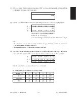
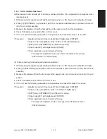
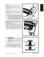
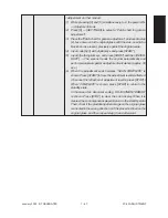
(c) Reproduction ratio adjustment of secondary scanning direction (Fine adjustment of transfer belt mo-
tor rotation speed)
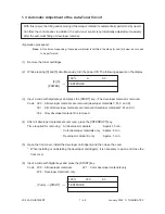
1. While pressing the digital keys [0] and [5] simultaneously, turn ON the power.
→
(Adjustment mode)
2. Press [1]
→
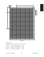
[SETTINGS]. (A grid pattern illustrated later is printed out. Use A3 (LD) from the 2nd
cassette.)
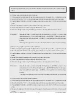
3. Measure the distance C from the 6th to 26th grid lines of the grid pattern.
4. Check if the distance C is within 200 ± 0.5 mm or not.
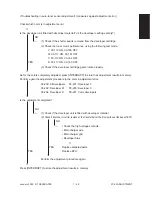
5. If it is not, use the following procedure to change values and repeat the steps 2 to 4 above.
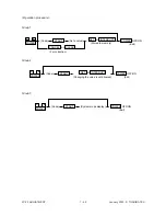
<Procedure>
(Adjustment mode)
→
(Input code [401] with digital keys)
→
[START]
→
(Input a value (ac-
ceptable values: 1327 to 1382) with digital keys)
→
[SET] icon or [INTERRUPT] key
(Stored in memory).
→
(Input code [407] with digital keys)
→
[START]
→
Color registration
control forced performing
*The larger the adjustment value, the shorter the distance C becomes (0.074 %/step =
0.15 mm/step).
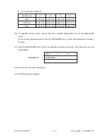
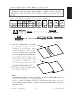
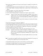
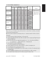
(d) Secondary-scanning data write start position adjustment
1. While pressing the digital keys [0] and [5] simultaneously, turn ON the power.
→
(Adjustment mode)
2. Press [1]
→
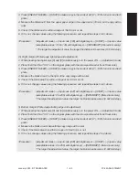
[SETTINGS]. (The following grid pattern is printed out. Use A3 (LD) from the 2nd cassette.)
3. Measure the distance D from the leading edge of the paper to the 6th grid line of the grid pattern.
4. Check if the distance D is within 55 ± 0.5 mm or not.
5. If it is not, use the following procedure to change values and repeat the steps 2. to 4. above.
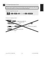
<Procedure>
(Adjustment mode)
→
(Input code [474] with digital keys)
→
[START]
→
(Input a value (ac-
ceptable values: 0 to 15) with digital keys)
→
[SET] icon or [INTERRUPT] key (Stored in
memory).
→
(Input code [407] with digital keys)
→
[START]
→
Color registration control
forced performing
*The larger the adjustment value, the shorter the distance D becomes (0.6 mm/step).
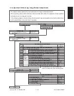
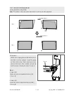
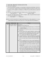
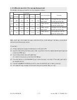
Note: The reproduction ratio adjustment and the data write start position adjustment in the primary and
secondary scanning directions have a connection as shown below.
1. When [05-400] is adjusted, [05-401, 402, 403, 404 and 474] are automatically adjusted.
2. When [05-401] is adjusted, [05-402, 403, 404 and 474] are automatically adjusted.
3. When [05-406] is adjusted, [05-404] is automatically adjusted.
Summary of Contents for FC22
Page 115: ...FC 22 PREVENTIVE MAINTENANCE 2 8 January 2000 TOSHIBA TEC Front side drive system 47 20 ...
Page 121: ......
Page 235: ...January 2000 TOSHIBA TEC 5 29 FC 22 FIRMWARE UPDATING ...
Page 237: ...FC 22 SERVICE HANDBOOK 6 WIRE HARNESS CONNECTION DIAGRAMS 6 2 DC Wire Harness ...
Page 238: ...FC 22 WIREHARNESS CONNECTION DIAGRAMS 6 3 January 20000 TOSHIBA TEC ...

