background image

FC-22 ADJUSTMENT

1 - 72

January 2000  ©  TOSHIBA TEC

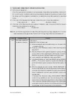
(b)

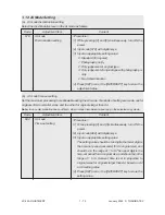
AI mode time-out setting

Set the maximum processing time allowable during the AI mode. Two kinds of setting are made, one for

originals of A4 or smaller sizes, and the other for originals larger than A4.

Note: In case discrimination does not finish, stop AI mode discrimination and copy in the selected copy mode.

Code

Adjustment item

Content

682

AI mode

Time-out setting

<Procedure>

(1)  While pressing [0] and [5] simultaneously, turn ON the

power.

(2) Input code [682] with digital keys.

(3) Input an appropriate setting value:

The setting value should be two digits; the lower digit is

the time-out period (seconds) for A4 original size, and

should be in the range of 1 to 9. The upper digit is the

time-out period for A3 original size, and should be in the

range of 1 to 9. However, time is set in proportion to

original sizes for originals larger than A4, based on A4

or A3 setting value.

(4) Press [SET] icon or the [INTERRUPT] key to store the

setting value.

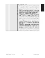
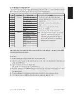
1. 12  AI Mode Setting

(a)

AI mode discrimination setting

Select the discrimination level in the AI mode as follows:

Code

Adjustment item

Content

678

AI mode

Discrimination setting

<Procedure>

(1) While pressing [0] and [5] simultaneously, turn ON the

power.

(2) Input code [678] with digital keys.

(3) Input an appropriate setting value:

       0 : Standard (for regular)

       1 : Photograph priority

       2 : Only judgement of original type

       3 : Only judgement of original type with photograph pri-

ority

       4 : No AI discrimination

(4) Press [SET] icon or the [INTERRUPT] key to store the

adjustment value.

Summary of Contents for FC22

Page 1: ... during service Be sure not to touch high temperature sections such as the exposure lamp the fuser unit the damp heater and their periphery Be sure not to touch high voltage sections such as the chargers the transfer belt and the high voltage transformer Be sure not to touch rotating operating sections such as gears belts pulleys fan etc When servicing the machines with the main switch turned on b...

Page 2: ...rong places 7 Basically the machine should not be operated with any parts removed or disassembled 8 Precautions Against Static Electricity The PC board must be stored in an anti electrostatic bag and handled carefully using a wrist band because the ICs on it may become damaged due to static electricity Caution Before using the wristband pull out the power cord plug of the copier and make sure that...

Page 3: ...1 ADJUSTMENT ITEMS 2 PREVENTIVE MAINTENANCE PM 3 PRECAUTIONS FOR STORING HANDLING SUPPLIES 4 TROUBLESHOOTING 5 FIRMWARE UPDATING 6 WIRE HARNESS CONNECTION DIAGRAMS ...

Page 4: ...ated adjustment 1 58 1 7 Automatic Adjustment of Gamma Correction 1 66 1 8 Density Adjustment 1 68 1 9 Color Balance Adjustment 1 69 1 10 Offset Amount for Processing Background 1 70 1 11 Judgment Threshold for ACS 1 71 1 12 AI Mode Setting 1 72 1 13 Sharpness Adjustment 1 73 1 14 High Voltage Transformer Setting 1 74 1 14 1 Overview 1 74 1 14 2 Settings after replacing main high voltage transform...

Page 5: ...ration sensor after feeding 4 5 4 1 4 Cover open jam 4 6 4 1 5 Paper jam in ADU and reversing area 4 8 4 1 6 Original jam in the RADF 4 10 4 1 7 Paper jam in the sorter 4 12 4 1 8 Special sheet jam 4 15 4 1 9 Drive system related service call 4 16 4 1 10 Paper feeding system related service call 4 20 4 1 11 Scanner related service call 4 23 4 1 12 Copy process related service call 4 25 4 1 13 Fuse...

Page 6: ...ugh PC 5 14 5 2 1 Outline 5 14 5 2 2 System configuration 5 14 5 2 3 Preparation of PC to use a network 5 15 5 2 4 Installation of FTP server 5 25 6 WIRE HARNESS CONNECTION DIAGRAMS 6 1 6 1 AC Wire Harness 6 1 6 2 DC Wire Harness Appendix III January 2000 TOSHIBA TEC FC 22 CONTENTS ...

Page 7: ...rom the 3rd cassette E25 Paper transport jam from the 4th cassette Cover open jam E41 Front cover opened during copying E42 Side door opened during copying E43 ADU unit pulled out during copying E45 LCF jam access cover opened during copying E46 Bypass unit opened during copying E50 Paper not reaching the ADU E51 Paper not restarting from the ADU stack E52 Paper not reaching the ADU path sensor E5...

Page 8: ...addle delivery failure Special sheet jam EC2 OHP sheets used except from bypass and 2nd cassette EC3 OHP sheet used in non OHP mode Drive system related service call C05 ADU motor rotation abnormal C09 Black developer motor rotation abnormal C0A Color developer motor rotation abnormal C0B Drum motor K rotation abnormal C0C Drum motor C rotation abnormal C0D Drum motor M rotation abnormal C0E Drum ...

Page 9: ...r function abnormal C35 Transfer belt unit contact release function abnormal C37 Transfer belt moter rotation abnormal C38 Auto toner initializing error K C39 Auto toner initializing error C C3A Auto toner initializing error M C3B Auto toner initializing error Y C3C Main charger wire abnormal K C3D Main charger wire abnormal C C3E Main charger wire abnormal M C3F Main charger wire abnormal Y ...

Page 10: ...ror C7 Communications related service call C57 Communications error between Main CPU and Sorter CPU C5A Communications error between Main CPU and printer controller C5B Main CPU signal transmission error to IMC CPU C5C Main CPU signal reception error from IMC CPU ADF related service call C72 Error of aligning sensor automatic adjustment C73 EEPROM initializing error C74 Error of paper exit sensor ...

Page 11: ... Saddle folding motor abnormal CBF Saddle positioning plate motor abnormal CC0 Sensor connector connection abnormal CC2 Micro switch abnormal Sorter related service call CC1 Transport motor rotation abnormal CC3 Bin shift motor rotation abnormal CC4 Guide bar swing motor rotation abnormal CC5 Staple unit swing motor rotation abnormal CCA Automatic adjustment error of bin inside paper sensor CCC No...

Page 12: ...ontent Options related service call F07 Communications error between System CPU and Main CPU F11 Communications error between System CPU and Scanner CPU F51 Communications error between System CPU and AI board during pre scanning Image processing options related service call ...

Page 13: ... sort D DF mode 0 Unused 1 AUTO FEED SADF 2 STACK FEED E APS AMS mode 0 Not selected 1 APS 2 AMS F Duplex mode 0 Not selected 1 BOOK 2 Two sided Single sided 4 Two sided Duplexed 8 Single sided Duplexed G Unused H Binding space 0 Unused 1 BOOK 2 LEFT 4 RIGHT I Editing 0 Unused 1 Masking 2 Trimming 3 Mirror image 4 Negative Positive J Edge erase Dual page 0 Unused 1 Edge erase 2 Dual page 3 Edge er...

Page 14: ...usly the two digital keys corresponding to the mode you want to set for example 0 and 5 turn on the main switch POWER 0 1 CLEAR CLEAR POWER OFF ON All control panel LEDs light Power Check Key Exit Exit or START START Operation procedure Whole control panel lighting mode 01 Notes 1 During the Check keys mode CLEAR alone can do During the Whole control panel lighting mode CLEAR can clear the mode 2 ...

Page 15: ...pressing CLEAR to make the copier ready you can make copies 2 After having used the self diagnostic mode be sure to turn OFF and then ON the power before returning the copier to the customer Normal Warming up Standby CLEAR 0 1 All the displays on the control panel lit 0 3 0 5 0 8 Setting mode Adjustment mode Test mode Power ON Test print mode Power OFF ON Hand over to user 2 1 0 4 ...

Page 16: ...lower 0 Switch is ON C Paper size switch 2 2nd cassette Middle upper 0 Switch is ON 2 D Paper size switch 3 2nd cassette Upper 0 Switch is ON E Cassette paper empty sensor 2nd cassette 1 No paper F Cassette tray up limit sensor 2nd cassette 1 Tray is upper limit G Cassette feed jam sensor 2nd cassette 1 Paper exist H A Paper size switch 0 3rd cassette Lower 0 Switch is ON B Paper size switch 1 3rd...

Page 17: ...tion status 0 Normal rotation Motor is rotating by 03 Output mode H ADU unit is installed or not 0 ADU unit is installed A ADU paper jam switch 1 Paper exist B ADU paper empty switch 0 No paper C ADU end switch 1 End guide is positioned at home position 7 D ADU side switch 1 Side guide is positioned at home position E F Total counter is installed or not 0 Total counter is installed G Key copy coun...

Page 18: ... H IPC IF board Sorter installation kit is installed or not 0 Board installed A ADU path sensor 1 Paper exist B C Exit sensor 1 Paper exist 0 D Paper exit unit open close switch 1 Paper exit unit is open E Toner bag limit sensor 1 Used toner full F G H Table 1 Relation between bypass paper width sensor status and paper width size Bypass paper width sensor Paper width size 3 2 1 0 0 1 1 1 A3 LD 1 0...

Page 19: ...home position switch Y 0 Cleaning pad is positioned at home position B Wire cleaner home position switch M 0 Cleaning pad is positioned at home position C Wire cleaner home position switch C 0 Cleaning pad is positioned at home position 3 D Wire cleaner home position switch K 0 Cleaning pad is positioned at home position E Wire cleaner limit switch Y 0 Cleaning pad is positioned at limit position ...

Page 20: ... center check Thermistor output value is displayed with 8 bit Digital key Icon Item Condition 1 Lower fuser roller thermistor rear check Thermistor output value is displayed with 8 bit 2 Temperature sensor check Sensor output value is displayed with 8 bit 3 Humidity sensor check Sensor output value is displayed with 8 bit 4 Drum thermistor Y check Thermistor output value is displayed with 8 bit 5 ...

Page 21: ...e sensor 1 F G ADF size sensor 2 H ADF unit is installed or not 1 ADF unit is installed A B Direct control panel connection detection C Connection 7 D Installation E F Carriage home position sensor 1 Carriage is home position G Direct control panel SW F key during debugging H Platen sensor 1 Platen cover is closed A B C 8 D APS sensor APS R 1 Original exist E APS sensor APS C 1 Original exist F AP...

Page 22: ...alue is displayed with 8 bit 4 Auto toner sensor K Sensor output value is displayed with 8 bit 5 6 7 8 9 0 FULL COLOR key ON AUTO COLOR key OFF ENERGY SAVER key OFF Operation procedure Note After initialization the copier goes into the test mode 0 3 POWER OFF ON POWER LCD ON Exit START FULL COLOR AUTO COLOR ENERGY SAVER Digital keys Note When icon is displayed with white letter on black background...

Page 23: ...1 113 Toner motor K ON 163 Code No 113 function OFF 1 114 Image quality sensor shutter solenoid ON 164 Code No 114 function OFF 1 130 Polygonal motor standby speed ON 180 Code No 130 function OFF 1 131 Polygonal motor normal speed ON 181 Code No 131 function OFF 1 132 Image quality sensor LED ON 182 Code No 132 function OFF 1 133 Color registration sensor LED front ON 183 Code No 133 function OFF ...

Page 24: ...28 ADU end motor ON OFF 3 235 Main charger Y ON OFF 3 236 Main charger M ON OFF 3 237 Main charger C ON OFF 3 238 Main charger K ON OFF 3 239 Developer bias Y DC ON OFF 3 240 Developer bias M DC ON OFF 3 241 Developer bias C DC ON OFF 3 242 Developer bias K DC ON OFF 3 243 Developer bias Y DC ON OFF 3 244 Developer bias M DC ON OFF 3 245 Developer bias C DC ON OFF 3 246 Developer bias K DC ON OFF ...

Page 25: ...ing high speed ON OFF 3 302 SCM fan motor rotation speed Low High 3 304 Scanner exposure lamp ON OFF 4 331 ADF pick up roller rotation ON OFF 3 332 ADF aligning roller rotation ON OFF 3 333 ADF transport belt CW rotation ON OFF 3 334 ADF transport belt CCW rotation ON OFF 3 351 Scan motor carriage 1 reciprocating 3 352 Document motor indicator 1 reciprocating 3 353 ADF single sided original feedin...

Page 26: ...R OFF ON POWER Code Code Operation ON START START Operation OFF Exit 0 3 POWER OFF ON CLEAR POWER Code Exit One direction operation START 0 3 POWER OFF ON CLEAR POWER Code Operation ON Operation OFF START START Exit 0 3 POWER OFF ON CLEAR POWER Code 6 sec later or Operation ON Operation OFF START START Exit ...

Page 27: ...rn width 1 dot Pitch 5mm A3 LD adjustment pattern same as the adjustment pattern by 05 mode 1 SETTINGS 219 6 test pattern 220 8 test pattern None 230 Gradation check pattern 2 Pixels standard Pattern width 10mm A3 LD 32 gradation steps 231 Gradation check pattern 3 Pixels standard Pattern width 10mm A3 LD 32 gradation steps 234 Half tone A3 LD 256 Density check pattern A3 LD 291 2 pixel modulation...

Page 28: ...ginal stop position 8 0 15 original stops When the value in reverse side of two sided original creases by 1 the original stop po sition shifts by 1 mm away from the original stopper 137 RADF sensor automatic adjustment and By pressing the START key WAIT EPROM Initialization is displayed while the automatic adjustment is performed Perform RADF EPROM Initializa tion when EPROM RADF logic PWA or sens...

Page 29: ...eloper material and automatic ad justment of the auto toner cir cuit Developer bias DC output adjustment As the value increases the transformer output increases The adjustment value becomes effective only when the setting mode 08 400 401 409 is 0 disabled Main Automatic adjustment of the auto toner circuit Without automatic filling of developer material Auto toner sensor output is adjusted approx ...

Page 30: ... 1 1 1 1 1 1 1 1 1 1 1 1 1 1 1 1 1 1 1 1 4 4 4 4 4 4 4 4 1 1 1 1 1 Transfer bias output adjustment Normal paper mode Topface thick paper 1 mode The bias value of the transfer roller is set The higher the value the larger the transformer output be comes The adjustment value be comes effective only when the set ting mode 08 400 401 409 is 0 disabled Normal paper mode Re verse face Thick paper 2 mode...

Page 31: ...0 059 404 Fine adjustment of feed motor rotation speed 4289 0 65535 When the value increases by 1 the rotation speed of the paper feed motor decreases by 0 023 406 Feed motor speed adjustment The paper transport speed of reg istration roller in relation to the im age printing speed is set at the op timum value If the value of this code 406 is performed the value of code 05 404 is optimized 407 Col...

Page 32: ...tration status display 0 0 255 The value ofY 0 shows the status of color registration sensor error 0 or 16 or above Normal 1 14 Data abnormal sensor normal 15 Color registration pattern reading error 470 K 100 0 255 When the value increases by 1 the image shifts by approx 0 042mm toward the right side of paper feed direction 474 8 1 15 When the value increases by 1 the image shifts by approx 0 6mm...

Page 33: ... Screen angle change Y 0 0 255 1 506 Screen angle change M 0 0 255 1 507 Screen angle change C 0 0 255 1 508 Screen angle change K 0 0 255 1 509 Modulation data results indication 0 8bit 4 4 5 10 511 Density adjustment density curve input full color 0 0 255 4 512 Density adjustment density curve selection 0 0 255 1 full color 513 Density adjustment density curve selection 0 0 255 1 full color 514 ...

Page 34: ...utput ON OFF switching 0 255 1 530 Filter coefficient set selection table 0 99 62 4 531 Scanner characteristic R for filter selection 0 8 1 532 Scanner characteristic G for filter selection 0 8 1 533 Scanner characteristic B for filter selection 0 8 1 534 Scanner correction color conversion matrix 0 15 selection 535 Basic color conversion matrix selection type A 0 255 1 536 Basic color conversion ...

Page 35: ...0 255 1 560 Full color Text Photo 20 0 255 1 561 Text 20 0 255 1 562 Printed image 20 0 255 1 563 Photo 20 0 255 1 564 Map 20 0 255 1 565 Black Text Photo 20 0 255 1 566 Text 20 0 255 1 567 Printed image 20 0 255 1 568 Photo 20 0 255 1 569 Map 20 0 255 1 Manual density fine adjustment Center setting When the value increases images made at center density become darker Manual density fine adjustment...

Page 36: ... 128 0 255 585 Black Text Photo 128 0 255 586 Text 128 0 255 587 Printed image 128 0 255 588 Photo 128 0 255 589 Map 128 0 255 604 Indication of calculation results for color 32bit 3 4 10 conversion matrix within design type A 605 Indication of calculation results for color 32bit 3 10 9 10 conversion matrix within design type B 606 Indication of calculation results for color 32bit 3 10 9 10 conver...

Page 37: ...43 Automatic adjustment of gamma correction Auto correction of gradation r 13 eproduction for each color Y M C K 646 Calculation results indication γ correction table 8bit 65 4 10 creation for 1 pixel CMYK 647 Calculation results indication γ correction table 8bit 65 4 10 creation for 2 pixels CMYK 648 Calculation results indication γ correction table 8bit 65 4 10 creation for 3 pixels CMYK 649 Ca...

Page 38: ...72 Differential threshold R G for ACS 0 0 255 1 673 Differential threshold G B for ACS 0 0 255 1 674 Differential threshold B R for ACS 0 0 255 1 675 Judgement threshold for ACS 104 0 0 255 When the value increases originals 1 tend to be judged as monochrome and when the value decreases they tend to be judged as color in auto color mode 676 Indication of results for ACS 2 677 Outputting of results...

Page 39: ... 1 Offset amount for processing back ground Text den sity adjustment When the value increases the text becomes denser 698 Full color Text Photo 128 0 255 699 Text 128 0 255 700 Printed image 128 0 255 701 Photo 128 0 255 702 Map 128 0 255 703 Black Text Photo 128 0 255 704 Text 128 0 255 705 Printed image 128 0 255 706 Photo 128 0 255 707 Map 128 0 255 708 Full color Text Photo 128 0 255 709 Text ...

Page 40: ...esults output 0 0 1999 1 color 729 Micro recognition Recognition results output 0 0 1999 1 monochrome 730 Sharpness Full color Text Photo text area 0 0 31 1 731 adjustment Text Photo photo area 0 0 31 1 732 AI text area 0 0 31 1 733 AI photo area 0 0 31 1 734 Text 0 0 31 1 735 Printed image 0 0 31 1 736 Photo 0 0 31 1 737 Map 0 0 31 1 January 2000 TOSHIBA TEC 1 27 1 FC 22 ADJUSTMENT When the value...

Page 41: ...ack ratio adjustment type D 0 0 255 1 761 Black table adjustment type A 0 0 77 1 762 Black table adjustment type B 0 0 77 1 763 Black table adjustment type C 0 0 77 1 764 Black table adjustment type D 0 0 77 1 765 Black calculation reference amount 1 0 Difference between maximum 1 specification type A and minimum 1 Minimum 766 Black calculation reference amount 1 0 Difference between maximum 1 spe...

Page 42: ...7 0 4 787 1 4 787 2 4 788 0 4 788 1 4 788 2 4 Text Photo Text Printed image Photo Map Text Photo Text Printed image Photo Map Low density Medium density High density Low density Medium density High density Low density Medium density High density Low density Medium density High density Low density Medium density High density Low density Medium density High density Low density Medium density High de...

Page 43: ...h density 128 0 255 128 0 255 128 0 255 128 0 255 128 0 255 128 0 255 128 0 255 128 0 255 128 0 255 128 0 255 128 0 255 128 0 255 128 0 255 128 0 255 128 0 255 128 0 255 128 0 255 128 0 255 128 0 255 128 0 255 128 0 255 128 0 255 128 0 255 128 0 255 128 0 255 128 0 255 128 0 255 128 0 255 128 0 255 128 0 255 Acceptable Operation Code Description Mode Default Value Contents procedure group When the...

Page 44: ...splays the output value of image quality sensor when the sensor light source is OFF Displays the output value of image quality sensor when there is no test pattern on the transfer belt Displays the output value of image quality sensor when a low density test pattern is written Displays the output value of image quality sensor when a high density test pattern is written The sensor s LED light amoun...

Page 45: ...OFF ON ENERGY SAVER START 0 5 POWER Code Auto adjustment START INTERRUPT Stored in memory Test copy Exit POWER OFF ON ENERGY SAVER START Group 4 0 5 POWER OFF ON POWER Code Exit Set a value START SET INTERRUPT or Stored in memory CLEAR or CANCEL For correction ENERGY SAVER START Test copy 0 5 POWER Code A value displayed START SET INTERRUPT or Changing the value not allowed Test copy Exit POWER OF...

Page 46: ...py Exit POWER OFF ON ENERGY SAVER START 0 5 POWER Code Auto adjustment START Test copy Exit POWER OFF ON ENERGY SAVER START Code Sub code START START START SET INTERRUPT or Changing the value not allowed 0 5 POWER Test copy Exit POWER OFF ON ENERGY SAVER START Set 5 adjustment charts for bypass Code Auto adjustment Jam or Error START INTERRUPT 0 5 POWER Exit Stored in memory POWER OFF ON CLEAR Gro...

Page 47: ...counter 204 Auto clear time setting 3 FC22 0 10 Time out for cleaning control panel settings 0 FC25P and returning to the default settings 0 Disabled 1 to 10 Set number x 15 second 205 Energy saver timer setting 0 0 15 FC15 22 Timer for switching from Ready mode to 0 19 FC25P Energy Saver selected code 618 0 Disabled 1 30sec 2 60sec 3 90sec 4 120sec 5 150sec 6 3min 7 4min 8 5min 9 7min 10 10min 11...

Page 48: ...e number up to 14 digits can be entered Use the HELP key to enter hy phens 253 Error code history display 256 LCF paper size 0 0 1 0 A4 1 LT Timer for Print job start up time from copy mode when auto clear is disabled All clearing by key copy counter removal Telephone number for Call for service 212 Bypass paper default type 0 0 Plain paper 1 OHP 1 2 A3 wide 3 Thick paper 1 4 Thick paper 2 5 Thick...

Page 49: ...ty control 1 1 0 1 Auto performing of image quality control 0 Disabled 1 Enabled Performing 08 410 413 Maximum number of copies allowed Resettable 1 269 0 0 1 0 Disabled 1 Enabled Forced performing of image quality control before the use level calibration Copy and Original counter display UC 0 EUR 3 Switch back RADF Non standard size original detection 350 Manually placed original 0 0 Not present ...

Page 50: ...is attained new image quality control automatically starts after the current print ing job 0 Disabled 1 Enabled Setting value of 08 455 409 Image quality control 3 1 0 1 Auto performing of image quality control 0 Disabled 1 Enabled Performing 08 410 413 410 1 0 1 Performing drum temperature compensa tion for image quality control 0 Disabled 1 Enabled When Image quality controls 1 and 3 08 400 409 ...

Page 51: ...matically switch to that source of paper 485 0 0 1 Setting of pre running rotation of polygo nal motor 0 Low speed rotation Pre running rotation 1 Stop 491 Out of specified paper size printing 0 0 1 0 Disabled 1 Enabled 505 Paper plain paper OHP thick 1 0 Compatible paper not present paper 1 Compatible paper present Switched according to image processing 507 Filter setting selection in Fiery 0 0 1...

Page 52: ...ion ratio adjustment 603 Automatic duplexing mode 0 0 3 0 Disabled 1 Single sided to Duplexed 2 Two sided to Duplexed 3 User selection 604 APS Automatic Paper Selection 0 0 2 0 APS mode 1 AMS mode 2 None AMS Automatic Magnification Selection Mode priority at power on 605 SAPS mode 1 0 All originals detected 1 First original only 606 Edge erase default setting 0 0 Invalid 1 Valid ...

Page 53: ... 0 0 1 0 Without shift 1 With shift 618 Energy saver mode 0 0 1 0 Energy saver mode with priority aim of energy saving Refer to 08 712 1 Energy saver mode with priority aim of returning to copying Refer to 08 713 619 10 0 50 620 APS forced start setting selection 0 0 2 0 Single press of key 1 Double press of key 2 Disabled 624 Cut width for all area copying 0 0 2 mm unit 0 1 625 Blank paper preven...

Page 54: ... 669 All clearing of image processing 3 05 adjustment values 670 All clearing of halfway results 3 of color conversion 671 All clearing of pulse width 3 selection adjustment results 672 All clearing of γ correction 3 table adjustment results 678 Mode memory initialization 3 679 Weekly timer initialization 3 681 Support for cascading exit 0 1 0 Invalid 1 Valid 1 682 Auto job start Magazine sort 0 0...

Page 55: ... 802 is reflected 806 Black print counter Copier 0 0 999999 Display of counter value Code 08 802 is reflected 807 Mono color print counter Copier 0 0 999999 Display of counter value Code 08 802 is reflected 808 Bypass counter 0 0 999999 Display of counter value Single count for every paper size 809 LCF counter 0 0 999999 Display of counter value Single count for every paper size 810 Full color pri...

Page 56: ...er 3 PPC Printer 832 1st cassette counter 0 0 999999 Paper feed counter of 1st cassette Display of counter value Single count for every paper size 833 2nd cassette counter 0 0 999999 Paper feed counter of 2nd cassette Display of counter value Single count for every paper size 834 3rd cassette counter 0 0 999999 Paper feed counter of 3rd cassette Display of counter value Single count for every pape...

Page 57: ...de 08 858 is reflected 0 clearing 854 0 0 999999 Number of printed sheets Display of counter value Code 08 858 is reflected 0 clearing 855 0 0 999999 Number of printed sheets Display of counter value Code 08 858 is reflected 0 clearing 856 0 0 999999 Rotation time of fuser motor sec Display of counter value 0 clearing 857 Counter setting for PM 0 0 999999 Counter value number or sheets 858 OHP thi...

Page 58: ...e motor sec Display of counter value 0 clearing 870 0 0 999999 Rotation time of K drum drive motor sec Display of counter value 0 clearing 871 0 0 999999 Rotation time of color development motor sec Display of counter value 0 clearing 872 0 0 999999 Rotation time of color development motor sec Display of counter value 0 clearing 873 0 0 999999 Rotation time of color development motor sec Display o...

Page 59: ...ion Code Name Default input value Contents procedure group 1 2 2 2 2 898 0 0 999999999 Rotation time sec of K drum drive motor Display of counter value 0 clearing 900 Firmware version Basic part ROM 902 Engine ROM version LGC 903 Engine ROM version IMC 904 SCAN ROM version 2 997 Long Short size counter List display of Money collection counter 08 876 885 Drum drive total counter for PM life time co...

Page 60: ...oup 2 Group 3 Code Set a value START SET INTERRUPT or Stored in memory CLEAR CANCEL or For correction 0 8 POWER Exit POWER OFF ON 0 8 POWER Code START SET INTERRUPT or Changing the value is not allowed Exit POWER OFF ON 0 8 POWER Code System mode display START Exit POWER OFF ON ...

Page 61: ...istered with digital keys Procedure for using the ID code mode 600 2 SET POWER OFF Dept control START 0 8 POWER 8 display Enter a 4 digit ID code Example 0525 ENERGY SAVER registered Up to 120 ID codes can be registered Input a next code ID registration mode completed 0525 0 0 0 0 Full color Black Mono color Total ID START START display Warming up Normal copy mode ENERGY SAVER registered POWER Pro...

Page 62: ...To finish the registration mode and return to normal copy mode 8 0525 0 0 0 0 START POWER ID Next ID code displayed displayed ENERGY SAVER registered Input an ID code While ENERGY SAVER HELP registered Input a counter value ENERGY SAVER HELP registered Input a counter value twice Press ENERGY SAVER HELP registered Input a counter value 3 times Press Warming up Normal copy mode START CLEAR display ...

Page 63: ...y scanning data write start position adjustment 474 7 Fine adjustment of feed motor rotation speed 404 8 a Image distortion adjustment 9 b Image skewing adjustment 10 c Primary scanning reproduction ratio scanner 482 11 d Scanner copy length reproduction ratio adjustment 104 12 e CCD primary scanning start position deviation 106 108 13 f Secondary scanning data write start position adjustment Copi...

Page 64: ... digital keys and press the START key 촞The developer material is removed Code 390 All developer materials are removed developer materials Y M C and K 391 All color developer materials are removed developer materials Y M and C 392 Only developer material K is removed 4 After all developer materials are removed press the INTERRUPT key Time required for removing All developer materials Approx 10 min ...

Page 65: ...nt sensor voltages V shown in 훾 automatically changes gradually approaching the target values for adjustment reference voltages shown in 훽 Values are displayed only for the developer materials being filled 9 In 30 to 60 seconds the current sensor voltages V in 훾 are converged to those in 훽 The humidity shown in 훿 disappears and the sensor output control values bit values are shown instead 훾 촞 Y 4 ...

Page 66: ... 26 4 36 10 If an adjustment error occurs values of the color in problem displayed in A B or C are replaced with As for properly adjusted colors press the INTERRUPT key to store their adjustment results in memory 11 Press the INTERRUPT key to store the adjustment results in memory The screen returns to the initial display 100 A A3 INTERRUPT 촞 TEST MODE 12 Remove the developer cartridge s 13 Instal...

Page 67: ...te properly 훹 As for the colors completely adjusted press INTERRUPT to store their adjustment results in memory Perform again the adjustment procedure to the color in adjustment error 05 200 All developers 05 201 Developer Y 05 202 Developer M 05 203 Developer C 05 204 Developer K 05 221 Color developers 훹 Is the adjustment completed NO 촞 1 Check if the developer unit is filled with developer mate...

Page 68: ...er than the above ones do the 05 878 Forced performing of image quality control procedure before automatic gamma value correction Code Adjustment item Content 878 Forced performing of Procedure image quality control 1 While pressing 0 and 5 simultaneously turn the power ON 촞 Adjustment mode 2 Input 878 with digital keys and press START 3 When the adjustment finishes normally the copier will return...

Page 69: ...art position adjustment 470 c Reproduction ratio adjustment of secondary scanning direction 401 Fine adjustment of transfer belt motor rotation speed d Secondary scanning data write start position adjustment 474 Fine adjustment of feed motor rotation speed 404 a Image distortion adjustment b Image skewing adjustment c Primary scanning reproduction ratio scanner 482 d Scanner copy length reproducti...

Page 70: ...ER SET INTERRUPT ENERGY SAVER Digital keys START Input codes Operation keys Display Varies with the code XXX entered with digital keys Current adjustment value Adjustment value newly input If no input YYY is displayed Power OFF ON Exit the adjustment mode Test copy Digital keys START Input adjustment values Value ZZZ is stored replacing values YYY If the test copy does not satisfy the specified va...

Page 71: ... Check for any transfer void or Z fold If a trans fer problem is present try the values in de scending order as 31 30 29 until the transfer void disappears At the same time confirm that any paper jam has not occurred Also when the aligning amount has been in creased this may increase the scraping sound which occurs when the paper scrapes on the mylar sheet as it is transferred by the regis tration...

Page 72: ...ng fused it it required to wait one or two minutes to cool them for precise adjustment Then set those five sheets again into the bypass tray in the same print direction with the chart face upward 5 Without changing the mode 05 enter 406 and press START While the adjustment chart sheets are fed and transported the pitches in the black belt zone are read 6 The step 5 is to be repeated five times aut...

Page 73: ... Input code 407 with digital keys START Color registration control forced performing The larger the adjustment value the shorter the distance A becomes 0 082 step 0 164 mm step b Primary scanning data write start position adjustment 1 While pressing the digital keys 0 and 5 simultaneously turn ON the power Adjustment mode 2 Press 1 SETTINGS A grid pattern with 10 mm squares is printed out Use A3 L...

Page 74: ...rt position adjustment 1 While pressing the digital keys 0 and 5 simultaneously turn ON the power Adjustment mode 2 Press 1 SETTINGS The following grid pattern is printed out Use A3 LD from the 2nd cassette 3 Measure the distance D from the leading edge of the paper to the 6th grid line of the grid pattern 4 Check if the distance D is within 55 0 5 mm or not 5 If it is not use the following proced...

Page 75: ...eeding direction Grid pattern Adjustment order 0 5 power ON 촞 1 촞 SETTINGS 2nd cassette A3 LD A 05 400 촞 200 0 5 mm 0 164 mm step 촞 05 407 B 05 470 촞 5 0 5 mm 0 042 mm step 촞 05 407 C 05 401 촞 200 0 5 mm 0 15 mm step 촞 05 407 D 05 474 촞 55 0 5 mm 0 6 mm step 촞 05 407 ...

Page 76: ...ss and the left top cover and then move the carriage 1 toward the paper exit side until it stops Insert a plus type screw driver into the hole of the indicator unit and ad just the screws following the step 1 to step 2 Step 1 In case of A Tighten the mirror 2 adjustment screw CW Go to C In case of B Loosen the mirror 2 adjustment screw CCW Go to D Image A B D Mirror 2 Feeding direction Feeding dir...

Page 77: ...ion Method of the Adhesive for the Screw Locking 1 Adjust the image distortion 2 Remove the original glass and the indicator unit 3 Move the carriage 1 toward the paper exit side 4 Apply the adhesive BOND 1324 to the adjust ment screws of carriage 1 and 2 Mirror Note Application Method Apply good quantity of the adhesive to the Ap plication area The adhesive needs 12 hours to harden com pletely 5 ...

Page 78: ...e copy image is tilted even when the original is placed precisely against the original scale adjust the original scale to correct this problem When the image is tilted as in A Adjust the original scale in the direction of the arrow A When the image is tilted as in B Adjust the original scale in the direction of the arrow B B A ...

Page 79: ...nt 1 While pressing the digital keys 0 and 5 simultaneously turn the power ON 촞 Adjustment mode 2 Place Test Chart No TCC 1 on the original glass with the arrow positioned at the left rear side 3 Press ENERGY SAVER 촞 START to make a copy in the mode of A4 LT 100 full color and text photo 4 Measure the distance B between M3 and M4 on the copy with a ruler 5 Check if the distance B is within a range...

Page 80: ...ft rear side 3 Press ENERGY SAVER 촞 START to make a copy in the mode of A4 LT 100 full color and text photo 4 Measure the distance D from the upper paper edge to the upper write start position on the copy with a ruler 5 Check if the distance D is within a range of 5 0 5 mm or not 6 If it is not change values using the following procedure and repeat the steps 3 to 5 above This adjustment should be ...

Page 81: ... copy image with a ruler 5 Check if the blank area F is within a range of 2 0 5 mm or not 6 If it is not change values using the following procedure and repeat the steps 3 to 5 above Procedure Adjustment mode 촞 Input code 427 with digital keys 촞 START 촞 Input a value acceptable values 0 to 255 with digital keys 촞 INTERRUPT Stored in memory The larger the adjustment value the larger the blank area ...

Page 82: ...ext photo A 05 482 촞 200 0 5 mm 0 2 mm step 촞 05 407 B 05 104 촞 150 0 5 mm 0 23 mm step 촞 05 407 C 05 106 촞 5 0 5 mm 0 042 mm step D 05 485 2nd 484 1st 486 3rd 487 4th 488 bypass 489 LCF and 490 ADU 촞 5 0 5 mm 0 6 mm step E 05 105 촞 10 0 5 mm 0 12 mm step F 05 427 촞 2 0 5 mm 0 042 mm step G 05 428 촞 2 5 0 5 mm 0 042 mm step Feeding direction Chart TCC 1 ...

Page 83: ...For checking color registration 6 Pictures For checking color reproduction and moire 7 Magnification lines For checking the magnification error of primary and secondary scan ning directions 8 Center lines Center lines for A4 LT sizes 9 Arrow A mark for placing the chart properly onto the original glass place it to the left rear corner of the original glass 10 Halftone band For checking uniformity ...

Page 84: ...justment of Text or Map mode 1 While pressing 0 and 5 simultaneously turn the power ON 촞 Adjustment mode 2 Press 4 촞 SETTINGS and output a Patch chart for gamma adjustment 3 Place the Patch chart for gamma adjustment produced in step 2 face down onto the original glass with the side on which a black band is present precisely against the original scale 4 Input code 643 with digital keys and press S...

Page 85: ...T 촞 The scanner reads the original automatically and performs automatic gamma adjustment calculation approx 30 sec 6 When the adjustment ends normally SCAN COMPLETE is shown Press START to have the adjustment results reflected To cancel the reflection of adjustment results press STOP When COMPLETE is shown press STOP to return to the standby state In the case of an abnormal ending ADJUSTMENT ERROR...

Page 86: ... the light side becomes The larger the value the darker the image becomes Manual density center value Manual density dark step value Manual density light step value Automatic density Manual density center value Manual density dark step value Manual density light step value Automatic density Black Make a test copy and compare the image obtained with the current settings if necessary make adjust men...

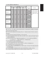
Page 87: ...ent settings if necessary make adjust ment using the following procedure Note Be sure that this adjustment be made after performing 1 7 Automatic Adjustment of Gamma Correction Procedure 1 While pressing 0 and 5 simultaneously turn the power ON 2 Input the code of required mode color mode copy mode item to be adjusted with digital keys and press the START key 3 Select the density area to be adjust...

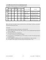
Page 88: ...for Processing Background The density of background and text can be adjusted as follows Make a test copy and compare the image obtained with the current settings if necessary make adjust ment using the following procedure Procedure 1 While pressing 0 and 5 simultaneously turn the power ON 2 Input the code of required mode color mode copy mode item to be adjusted with digital keys and press the STA...

Page 89: ... the original set on the glass is monochrome or color Namely this is to adjust the judgment level used when Auto color is selected in the color mode Code Adjustment item Content 675 Judgment threshold for ACS The larger the value the more an original tends to be judged to be monochrome and the smaller the value the more it tends to be judged to be color ...

Page 90: ...ze and should be in the range of 1 to 9 The upper digit is the time out period for A3 original size and should be in the range of 1 to 9 However time is set in proportion to original sizes for originals larger than A4 based on A4 or A3 setting value 4 Press SET icon or the INTERRUPT key to store the setting value 1 12 AI Mode Setting a AI mode discrimination setting Select the discrimination level...

Page 91: ...es 0 to 31 The center value is 16 However 0 is equivalent to the center value Note In the text photo and AI modes you can make adjustment for text area and photo area independently but in the other modes you have to make adjustment by compromising between moire and sharpness Make a test copy and compare the image obtained with the current settings if necessary make adjust ment using the following ...

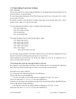
Page 92: ...y The main high voltage transformer and transfer transformer for service parts are supplied with the data sheets to be used for the following setup Be careful not to lose them Output adjustment is performed when the devices are shipped so under any circumstances do not move the resistors fixed to the board 1 14 2 Settings after replacing main high voltage transformers After replacing a main high v...

Page 93: ... Turn the power OFF 1 14 3 Settings after replacing transfer transformer After replacing a transfer transformer input the data shown on the supplementary data sheet transfer bias according to the procedure below without fail Settings for transfer roller bias 1 Turn the power ON while pressing 0 and 5 simultaneously 2 Input code 367 and press START key 촞 The lower limit value for transfer bias is d...

Page 94: ...eve Doctor blade Screws Gauge 0 55 of the doctor sleeve jig 3 Insert the gauge 0 55 of the jig into the gap between the sleeve and the doctor and make sure that the gauge can move smoothly in the front촟촞rear direction In addition confirm that the gauge 0 65 cannot be inserted into the gap Note 1 When confirming and adjusting the gap between the developer sleeve and the doctor blade insert the gaug...

Page 95: ...h on the front and rear sides of carriage 2 and fasten the screw on the front side of carriage 2 3 While placing the protruding parts of carriage 1 against the carriage jigs fasten carriage 1 to the wire on both front and rear sides 4 Pull out the carriage jigs Carriage 1 Front side Rear side b Adjusting the carriage drive wires Since the wires are applied with proper tension by tension springs th...

Page 96: ...the upper side 2 Wind the wires onto the wire pulleys on the front and rear The number of turns to be wound are as follows see the illustrations below One turn on the inside of the boss Six turns on the outside of the boss After winding the wires on the pulleys hold the wires with wire holder jigs to prevent them from unwinding Wire pulley Rear side Front side Ball terminal 1 turn 6 turns Hook Pul...

Page 97: ... are in firm contact with the surface of the pulley Each time you wind a turn on the pulley push it to the preceding turn so that all the turns are closely wound 2 When fitting wire holder jigs take care so that the turns wound on the pulleys do not move or unwind No gap should exist e g Front side Relationship between wound turns and wire holder jigs 3 mm dia ball terminal Pulley Wire holder jigs...

Page 98: ...adjusted in the field or some of its components must not be replaced If necessary the lens unit should be replaced as a unit While replacing with a new lens unit never loosen or remove the six screws indicated with arrows below They are locked with special paint Use sufficient care when handling the lens unit Never hold the precision adjusted area of the lens unit ...

Page 99: ... paper at 100 reproduction ratio 2 Compare the copied ruler with the actual ruler to measure the error in the reproduction ratio 3 Make adjustment so that the distance between each mark of both rulers becomes equal using the following procedure Note After this adjustment be sure to perform CCD primary scanning deviation adjustment Adjustment procedure 1 Remove the original glass lens cover damp he...

Page 100: ...fication ratio 8 Reinstall the damp heater unit lens shield bracket lens cover and original glass 4 Using the marks on the scanner base as a guide adjust the lens unit in either forward or backward direction The following table shows the error in the reproduction ratio between the copies and actual rulers compared to be measured and the amount of adjustment of the lens unit Reproduction ratio erro...

Page 101: ... unit 1 Insert the positioning pins front and rear into the hole of the lens unit and install to the scanner unit note As the shape of the front and rear differ pay attention to this point when installing parts 2 Fix the two oblong holes by two screws B two points B B ...

Page 102: ...ard the front or the rear by a maximum of 3 mm 2 If the copy image is shifted toward the rear of copy paper adjust the front cover of the cassette toward the front by the amount of the shift and fasten the screws 3 If the copy image is shifted toward the front of copy paper adjust the front cover of the cassette toward the rear by the amount of the shift and fasten the screws Left side Right side ...

Page 103: ...ation procedure 1 Remove the rear cover 2 Remove the feed side upper cover and cut open the window for the key copy counter 3 Pull out the harness connector from the hole in the machine frame and cut the shorting har ness of the connector Treat the cut harness properly to avoid it causing a short circuit with the machine frame Then disconnect the dummy connector Dummy connector Socket attachment s...

Page 104: ... machine 5 Install the counter socket to the machine frame with two M3 screws 6 Reinstall the feed side upper cover and the rear cover 8 In the 08 setting mode enter 3 under code 202 7 Insert the key copy counter with its arrow mark facing up and pointing toward the machine Socket connector Connector of the machine M3 screws ...

Page 105: ...n the value of the color PM counter 08 897 This maintenance which is performed with a focus on the color developer units should be con ducted in conjunction with the replacement cycle of the color developer materials FC 22 every 30K copies FC 15 every 20K copies The replacement cycle counter value of color maintenance is determined by the ratio of color copy to black copy as shown by the following...

Page 106: ...copies to confirm that the copier is working normally 2 3 Preventive Maintenance Checklist Symbols used in the checklist For FC 22 Cleaning Coating Replacing Operation check Date A Cleaning with alcohol Cleaning with soft pad cloth or vacuum cleaner W White grease Molycoat AV Alvania No 2 30 Every 30K copies 60 Every 60K copies 90 Every 90K copies 120 Every 120K copies Replace if deformed or damag...

Page 107: ...3 Main charger wire 60 7 P22 I15 14 Main charger grid 60 P22 I24 15 Main charger contact 60 16 Drum 60 5 P22 I38 17 Drum shaft 60 18 Drum thermister 60 19 Toner recovery auger drive 60 W 20 Toner cartridge drive gear W 21 Ozone filter 60 6 Around EPU P6 I37 area 22 Toner bag 30 Key operator s item P33 I33 23 Upper fuser roller 90 11 P27 I17 24 Lower fuser roller 90 12 P27 I4 25 Separation fingers ...

Page 108: ...on unit support bushings W 49 Original glass 60 or A 50 Platen cover 60 or A 51 Mirror 1 60 52 Mirror 2 60 53 Mirror 3 60 Scanner 54 Reflector 60 55 Lens 60 56 Exposure lamp 57 Original width indicator 58 Automatic original detection unit 59 Slide sheet 60 Air filter 60 61 Transfer belt 120 P30 I2 62 Transfer roller Y M C K 120 P30 I22 Transfer 63 Drive roller cleaning felt 120 P30 I27 transport u...

Page 109: ...als on both ends of the cleaning blade 60 9 Entire developer cleaner unit 60 8 10 Main charger case 60 7 11 Dischiarge LED 60 12 Wire cleaning pad 60 P22 I21 13 Main charger wire 60 7 P22 I15 14 Main charger grid 60 P22 I24 15 Main charger contact 60 16 Drum 60 5 P22 I38 17 Drum shaft 60 18 Drum thermister 60 19 Toner recovery auger drive 60 W Image quality 35 Image quality sensor s area 60 contro...

Page 110: ... 15 Main charger contact 40 16 Drum 40 5 P22 I38 17 Drum shaft 40 18 Drum thermister 40 19 Toner recovery auger drive 40 W 20 Toner cartridge drive gear W 21 Ozone filter 40 6 P6 I37 22 Toner bag 30 Key operator s item P33 I33 23 Upper fuser roller 60 11 P27 I17 24 Lower fuser roller 60 12 P27 I4 25 Separation fingers 60 14 P28 I31 26 Upper oil roller 20 13 P28 I56 27 Upper cleaning roller 20 13 F...

Page 111: ...ion unit support bushings W 49 Original glass 40 or A 50 Platen cover 40 or A 51 Mirror 1 40 52 Mirror 2 40 53 Mirror 3 40 Scanner 54 Reflector 40 55 Lens 40 56 Exposure lamp 57 Original width indicator 58 Automatic original detection unit 59 Slide sheet 60 Air filter 40 61 Transfer belt 120 P30 I2 62 Transfer roller Y M C K 120 P30 I22 Transfer 63 Drive roller cleaning felt 120 P30 I27 transport ...

Page 112: ...eals on both ends of the cleaning blade 40 9 Entire developer cleaner unit 40 8 10 Main charger case 40 7 11 Dischiarge LED 40 12 Wire cleaning pad 40 P22 I21 13 Main charger wire 40 7 P22 I15 14 Main charger grid 40 P22 I24 15 Main charger contact 40 16 Drum 40 5 P22 I38 17 Drum shaft 40 18 Drum thermister 40 19 Toner recovery auger drive 40 W Image quality 35 Image quality sensor s area 40 contr...

Page 113: ...2 6 January 2000 TOSHIBA TEC Front sectional view Processing unit EPU See next page 53 60 46 21 30 23 25 33 34 25 24 31 28 65 66 22 64 63 62 61 29 52 51 54 56 57 49 58 58 55 37 59 35 36 44 42 41 43 45 39 38 39 40 40 38 46 44 48 67 ...

Page 114: ...ocessing unit EPU 5 5 5 5 16 3 18 3 18 3 18 3 18 10 15 12 13 11 2 17 14 7 19 16 17 16 17 16 17 14 7 19 14 7 19 14 7 8 6 8 6 8 6 8 6 19 1 2 1 2 1 2 1 10 15 12 13 11 10 15 12 13 11 10 15 12 13 11 Developer unit K Developer unit C Developer unit M Developer unit Y ...

Page 115: ...FC 22 PREVENTIVE MAINTENANCE 2 8 January 2000 TOSHIBA TEC Front side drive system 47 20 ...

Page 116: ... latches of the developer unit cover gently and lift the cover up slowly Note Be careful not to allow the developer mate rial deposited on the back of the cover to drop into different color developer units To avoid this problem put paper over the other developer units not being cleaned now 6 Insert the doctor blade cleaning jig between the doctor blade and the sleeve and move the jig along the bla...

Page 117: ... from the EPU 3 Remove the developer unit cover Insert the doctor blade cleaning jig between the doctor blade and the sleeve and move the jig back and forth make 3 return movements to clean the doctor blade 4 After the cleaning return the developer re moval shutter lever to open the developer re moval opening move the lever in a direction reverse to 1 5 Making the developer removal opening point d...

Page 118: ...tom surfaces are dirty and clean if necessary 9 Developer material When the developer material is replaced be sure to perform automatic adjustment of the auto toner circuit adjustment mode 05 200 204 221 10 Drum seal Use a cloth which should be soaked in water and then wrung strongly to clean the front seal 11 Upper fuser roller Refer to 3 5 Checking and Cleaning of the Fuser rollers 12 Lower fuse...

Page 119: ...rger wire cleaning pad WIRE CH 310 4 60K kit 13 Main charger wire K PAD WIRE 4 60K 14 Main charger grid GRID CH 310 4 21 Ozone filter K FILTER OZN 1 23 Upper fuser roller HR FC22 U 1 24 Lower fuser roller HR FC22 L 1 FU KIT FC22 25 Separation finger SCRAPER PR 9 90K 90K kit 28 Lower oil roller SR FC22L 1 29 Lower cleaning roller B FC22L 1 38 Pick up roller cassette feed section K ROL PICK 310 1 61...

Page 120: ...ger wire cleaning pad WIRE CH 310 4 40K kit 13 Main charger wire K PAD WIRE 4 40K 14 Main charger grid GRID CH 310 4 21 Ozone filter K FILTER OZN 1 23 Upper fuser roller HR FC22 U 1 24 Lower fuser roller HR FC22 L 1 FU KIT FC22 25 Separation finger SCRAPER PR 9 60K 60K kit 28 Lower oil roller SR FC22L 1 29 Lower cleaning roller B FC22L 1 39 Pick up roller cassette feed section K ROL PICK 310 1 61 ...

Page 121: ......

Page 122: ... holder jig 100 2 ROM writer adapter 1 100 4 ROM writer adapter 2 100 8 Area sheet grid patterned sheet which 100 5 facilitates the reading of values on X Y coordinates in trimming and masking modes Doctor blade sleeve gap adjustment jig 100 3 Doctor blade cleaning jig 100 7 Cleaning brush 100 6 Test chart No TCC 1 100 9 Scanner carriage jig 100 10 ...

Page 123: ...stored horizontally on a flat surface F Copy Paper Avoid storing copy paper in places where it may be subjected to high humidity After a package is opened be sure to place and store it in a storage bag 3 2 Checking and Cleaning of the Photoconductive Drum 1 Use of Gloves If fingerprints or oil stain the OPC drum surface the characteristics of the photoconductor may degrade affecting the quality of...

Page 124: ... adverse effect on the drum Never use selenium refresher either 5 Scratches on Photoconductive Drum Surface If the surface is scratched to such a degree that the aluminum base is exposed black spots or streaks will be produced on copy images and can also damage the cleaning blade So replace the drum with a new one 6 Collecting Used Photoconductive Drums Regarding the recovery and disposal of used ...

Page 125: ...Handling Precautions Upper and lower fuser rollers Do not leave any oil fingerprints etc on the upper and lower fuser rollers Be careful not to allow any hard object to hit or rub against the fuser rollers or they may be damaged possibly resulting in defective cleaning 2 Checking Check for stain and damage on the fuser rollers and clean if necessary Clean the separation claws and check for chipped...

Page 126: ...from staining the belt surface Do not allow alcohol or any other organic solvent to come into contact with the transfer belt Do not apply external pressure that might scratch the transfer belt 3 7 Checking and Replacing the Transfer Roller 1 Handling Precautions Do not touch the transfer roller surface with your bare hands Be carefull not to leave any scratch or dent on the transfer roller surface...

Page 127: ...MC board and the SIC board are replaced at the same time the error code C9E might be displayed 4 1 Troubleshooting Based on Error Code 4 1 1 Paper transport jam inside the copier E01 Paper leading edge not reaching the exit sensor E02 Paper trailing edge not passing the exit sensor Is the fuser motor rotating Is the harness between the LGC board and the exit sensor open circuited Is the paper exit...

Page 128: ...tion sensor connector Repair if the actuator is displaced Before reaching the fuser unit Did the paper stop curling upward excessively Replace the paper in the cassette From on the transfer belt up to the exit sensor Do the size of paper and the size plate indication match Make the sizes match Is the transfer belt moving To C37 E03 Paper remaining inside the copier at power ON Is any paper remaini...

Page 129: ...aper remain within the specified paper weight and stack height Is there any foreign matter such as scrap of paper in the paper transport path from the bypass feed section up to the registration rollers Eliminate the foreign matter Check if the bypass pick up roller bypass feed roller or separa tion pad is not deteriorated Replace them if necessary Adjust the paper weight and stack height to follow...

Page 130: ...am sensor connector or the connector J107 on the LGC board discon nected Reconnect the connector Replace the harness 1 Replace the cassette feed jam sensor 2 Replace the LGC board E19 Paper misfeed from the LCF Open the side door does any paper remain in the paper path from the LCF Remove the paper Is the harness between the LGC board and the cassette feed jam sensor open circuited Is the cassette...

Page 131: ...te Open the side door does any paper remain in the paper path up to the registration roller Remove the paper Is the harness between the LGC board and the cassette feed jam sensor open circuited Is the harness between the LGC board and the registration sensor open circuited Is the cassette feed jam sensor connector registration sensor connector or the connectors J107 or J108 on the LGC board discon...

Page 132: ...ch main switch and the connector J709 of the switching power supply disconnected Reconnect the disconnected faston terminal or connector Replace the defective harness 1 Replace the front cover switch or the paper exit unit switch 2 Replace the main switch 3 Replace the switching power supply E42 Side door opened during copying Is the side door open Close the side door Is the harness between the LG...

Page 133: ...nnect the connector Replace the harness 1 Replace the LGC board 2 Replace the ADU unit E45 LCF jam access cover opened during copying Is the LCF jam access cover open Close the LCF jam access cover Is the harness between the LGC board and the LCF unit open circuited Is the relay connector of the harness between the LGC board and the LCF unit or the connector J105 on the LGC board disconnected Reco...

Page 134: ... harness 1 Replace the bypass unit open close switch 2 Replace the LGC board 4 1 5 Paper jam in ADU and reversing area E50 Paper not reaching the ADU E51 Paper not restarting from the ADU stack E54 ADU paper transport jam Is the ADU unit mounted securely on the copier Mount the ADU unit securely to the copier Is the connector J103 on the LGC board disconnected Is the harness between the LGC board ...

Page 135: ...DU path sensor Is the harness between the LGC board and the ADU path sensor open circuited Is the ADU path sensor connector or the connector J122 on the LGC board disconnected Reconnect the connector Replace the harness 1 Replace the ADU path sensor 2 Replace the LGC board NO YES ...

Page 136: ... mode E79 Prefeed jam Two or more originals are fed simultaneously Have too many originals been placed Reset the originals following the specification Are the original sheets curled or folded too much Flatten and reset the originals Are different size originals placed together Set only one size originals Is the gap between the aligning plate and the feed roller too large Adjust the gap Is the sepa...

Page 137: ...ps skewed on the original glass Is the aligning roller stained Clean the roller Is the transport belt stained Clean the belt Is the RADF correctly installed Properly install the RADF in parallel to the copier Make sure that the skew and height are properly adjusted The side edges of the original are out of alignment with the side edges of the copy Is the slides set too wide in relation to the widt...

Page 138: ...er sensor PI4 and sort paper sensor PI5 working normally Replace any faulty sensor Replace the sorter controller PC board EA2 Paper transport stop jam Is there any bur scratch or foreign matter on the paper transport path Remove any bur scratch or foreign matter Is the transport roller stained Clean the transport roller Are both non sort paper sensor PI4 and sort paper sensor PI5 working normally ...

Page 139: ...faulty sensor Replace the sorter controller PC board EA4 Sorter front door opened during copying Is the stapler unit cover securely closed Close the cover securely Is the sorter securely mounted on the copier Mount the sorter securely onto the copier Is the feed guide securely closed Close the feed guide securely Are the stapler cover open close switch MS5 joint switch MS1 and feed guide open clos...

Page 140: ...le jam Is there any jammed staple or foreign matter in the stapling area of the stapler unit Remove any jammed staple or foreign matter Is there any mar or damage in the stapling area Replace the stapler unit Replace the sorter controller PC board YES NO NO YES ...

Page 141: ...ecial sheet jam EC2 OHP sheets used except from bypass and 2nd cassette Use the 2nd cassette or the bypass as the feeding source of OHP sheets EC3 OHP sheet used in non OHP mode Set the specified type of paper as selected on the control panel in the paper source ...

Page 142: ... J101 J102 and J103 on the LGC board is disconnected 4 Reduce the mechanical load on the motor by adjusting the drive system Remove foreign matter if any 5 Replace the LGC board Are the pins B2 and B4 of the connector J103 on the LGC board always at the level L 1 Check if the connector J103 on the LGC board is disconnected 2 Check if any conductor pattern on the LGC board is open or short circuite...

Page 143: ...e the motor manually counterclockwise as seen from its back and if the motor load is abnormal remove any foreign matter from the drive unit Do not try to rotate the motor clockwise as seen from its back 8 Replace the black developer motor 9 Replace the LGC board Are the pins B12 and B15 of the connector J108 on the LGC board always at the level L 1 Check if the connector CN2 of the black developer...

Page 144: ...e the motor manually counterclockwise as seen from its back and if the motor load is abnormal remove any foreign matter from the drive unit Do not try to rotate the motor clockwise as seen from its back 8 Replace the color developer motor 9 Replace the LGC board Are the pins A12 and A15 of the connector J108 on the LGC board always at the level L 1 Check if the connector J41 of the color developer...

Page 145: ...or any open circuited harness or any disconnected connector pin 7 Rotate the motor manually counterclockwise as seen from its back and if the motor load is abnormal adjust the load on the drum shaft inside the EPU Remove any foreign matter from the drive unit Do not try to rotate the motor clockwise as seen from its back 8 Replace the LGC board 9 Replace the drum motor Are the pins K 22 pin C 28 p...

Page 146: ... the ADU drawer connector open circuited Reconnect the connector Replace the harness 1 Replace the LGC board 2 Replace the ADU unit C12 ADU paper end guide function abnormal Is the ADU unit mounted securely on the copier Mount the ADU unit securely onto the copier Is the timing belt for driving the paper end guide displaced Put the belt on properly Is the connector J103 on the LGC board disconnect...

Page 147: ... the cassette tray up motor open circuited Is the harness between the LGC board and the paper size switch open circuited Is the cassette tray up limit sensor connector cassette tray up motor connector paper size switch connector or connector J106 on the LGC board disconnected Is the peg of the paper size switch broken 1 Reconnect the connector 2 Replace any defective harnesses 3 Replace the paper ...

Page 148: ...en the LGC board and the LCF unit or the connector J105 on the LGC board disconnected Reconnect the connector Replace the harness Do the switches and sensors in the LCF unit function 1 Replace the LCF tray motor 2 Replace the LGC board 1 Replace any faulty sensor or switch in the LCF unit 2 Replace the LCF drive PC board or the LCF tray down switch PC board 3 Replace the LGC board NO YES NO YES ...

Page 149: ...loose 3 Check if any conductor pattern on the SDV board is open or short circuited 4 Check if any conductor pattern on the SCM board is open or short circuited 5 Replace the SDV board 6 Replace the SCM board C28 Does the carriage after arriving at its home position make a big noise Since the carriage home position sensor has not been turned ON 1 Check if the sensor connector is disconnected 2 Chec...

Page 150: ...uited conductor pattern 4 Check the SCM board for any open or short circuited conductor pattern 5 Replace the lens unit 6 Replace the SCM board 1 Check if the lamp connector is disconnected 2 Check if the thermostat is blown out 3 Check if the lamp has continuity 4 Check the SCM board if any pin of connectors J7 B1 B2 B4 B5 and B6 is disconnected or any harness is open or short circuited 5 Check t...

Page 151: ...tor connector disconnected Replace the harness Reconnect the connectors Is used toner jammed Is any abnormal mechanical load found 1 Remove the jammed used toner 2 Check for any foreign matter in the drive system 3 Check the bearing of the used toner transport auger for any abnormality 4 Check if the toner bag is covered with used toner 1 Replace the used toner transport motor 2 Replace the LGC bo...

Page 152: ... load by adjusting the drive system Remove any foreign matter Is the harness between the LGC board and the transfer transport unit drawer connector or the harness inside the transfer transport unit open circuited Is the transfer belt contact release drive motor connector LGC board connectors J115 or J102 transfer belt home position switch connector or transfer belt limit switch connector discon ne...

Page 153: ...pen circuited 6 Check for any open circuited harness or for any disconnected connector pin 7 Rotate the motor manually clockwise as seen from its back and if the motor load is abnormal adjust the load on the transfer belt unit Remove any for eign matter from the drive unit 8 Replace the LGC board 9 Replace the transfer belt motor Is the pin 15 of connector J116 on the LGC board always at the level...

Page 154: ...to toner initializing error Y Is the harness between the LGC board and the EPU drawer connector open circuited Is any harness inside the EPU or the auto toner sensor harness open circuited Is the auto toner sensor connector or the connector J119 on the LGC board disconnected Reconnect the connector Replace the harness 1 Replace the auto toner sensor 2 Replace the LGC board ...

Page 155: ... cleaner home position switch or the wire cleaner limit switch securely Is the main charger dislocated Is the wire cleaner home position switch or the wire cleaner limit switch disconnected 1 Reinstall the main charger 2 Reconnect the wire cleaner home position switch 3 Reconnect the wire cleaner limit switch Is the mechanical load too heavy 1 Check if the cleaning pad is in normal contact with th...

Page 156: ... 5 Check if the AC harness is open circuited 6 Check if SSR or the switching power supply is broken 3 Checking the LGC board 1 Check the LGC board if the connector J122 is disconnected 2 Check the LGC board for any abnormal condition such as an open or short circuited conductor pattern 3 Replace the LGC board 4 Clearing the status counter After completing the repair of what caused the problem C41 ...

Page 157: ... Clearing the status counter Since 5 is shown on the status counter rewrite it to 0 following the same procedure as in 4 of C41 C46 Heater abnormal low temperature after the copier has become ready 1 Checking the thermistors fuser lamps SSR and LGC board Check the thermistors fuser lamps SSR and LGC board following the same procedure as in 1 2 and 3 of C41 2 Clearing the status counter Since 7 is ...

Page 158: ...e procedure as in 4 of C41 C7 Error C7 To avoid any safety hazards be sure to unplug the power cord before proceeding to check the items in 1 and 2 below Be sure that the fuser unit is set in place securely 1 Check if any thermistor connector is disconnected 2 Check if any harness for the thermistors center and rear upper and lower is open circuited 3 Check the LGC board if the connector J122 is d...

Page 159: ...heck the IPC board for any open or short circuited conductor pattern 4 Check the harness connected to the connector J2 on the IPC board for any disconnected pin or any open circuit 5 Check if the switching power supply fuse F9 is blown out 6 Check the controller PC board inside the sorter for any open or short circuited conductor pattern 7 Check the connection between the sorter and the copier for...

Page 160: ... switching power supply is disconnected 5 Check the IMC and LGC boards for any open or short circuited conductor pattern 6 Replace the LGC board 7 Replace the IMC board For an external type printer controller 1 Check if the printer controller power is turned ON 2 Check if the harness between the PIF board and the printer controller is open circuited 3 Check if the PIF board is firmly connected to ...

Page 161: ... error to IMC CPU C5C Main CPU signal reception error from IMC CPU 1 Check if the harness between the LGC and IMC boards is open circuited and if the connector J113 on the LGC board and the connector J168 on the IMC board are disconnected 2 Replace the LGC board 3 Replace the IMC board ...

Page 162: ...EPROM and perform the sensor automatic adjustment C73 EEPROM initializing error 1 Check PWA F LGC 770 if any open or short circuit is present around IC7 2 Replace PWA F LGC 770 3 Initialize the RADF s EEPROM and perform the sensor automatic adjustment C74 Error of exit sensor automatic adjustment 1 Check if any foreign matter is present between the exit sensor and the reflecting mirror and if the ...

Page 163: ...en or short circuited 2 If this problem recurs frequently replace the LGC board C9E IMC board connection abnormal Is Call for service displayed again even after the copier is turned OFF and then back ON Observe the condition for a while 1 Check if the IMC board and the SIC board are firmly connected to the MTH board 2 Check the IMC board if the connectors J168 J162 J169 J165 J166 or J161 is discon...

Page 164: ... harness or disconnected connector pin 4 Check the IMC board for any open or short circuited conductor pattern 5 Replace the IMC board 6 Replace the laser optical unit Are both A2 and A3 pins of the connector J166 on the IMC board always at the level L 1 Check the IMC board for any open or short circuited conductor pattern 2 Replace the IMC board 3 Replace the laser optical unit 1 Check the IMC bo...

Page 165: ...CD2 Laser calibration error C CD3 Laser calibration error M CD4 Laser calibration error Y 1 Check if the harness between the IMC and RLY boards is open circuited 2 Check if the connector J162 on the IMC board is disconnected 3 Check if the connector J178 on the RLY board is disconnected 4 Check if the harness between the RLY board and the switching power supply is open circuited 5 Check if the con...

Page 166: ...en J6 1 and J6 2 on the harness side measure approx 5Ω Check the wiring up to the transport motor If it is normal replace the transport motor When manual stapling is done or when the push switch SW2 or SW3 on the sorter controller board is pressed does the voltage between J6 1 and J6 2 on the controller board measure approx 24V Replace the sorter controller board Reinstall the sorter firmly When t...

Page 167: ...rotate Check if the lead cam drive belt is properly fitted on the sprocket Disconnect J15 on the sorter controller board Does the resistance between J15 5 and J15 6 on the harness side measure approx 3Ω Check the wiring up to the bin shift motor M2 If it is normal replace the bin shift motor M2 Connect J15 on the sorter controller board Having tester probes touch J15 5 and J15 6 press SW2 does the...

Page 168: ...controller board Check the 24V power supply of the copier CC5 Stapler unit swing motor rotation abnormal At the time the stapler unit swings does the voltage between J9 1 and J9 2 on the sorter controller board show 24V Is a voltage of 24V being supplied from the copier Check the 24V power supply of the copier Replace the sorter controller board Is stapler unit swing switch MS9 working normally Re...

Page 169: ... the bin inside paper sensor is there any abnormality found Complete Replace the sorter controler board After having tried automatic adjustment of the bin inside paper sensor is there any abnormality found Complete Check if the bin inside paper sensor is installed securely After having tried automatic adjustment of the bin inside paper sensor is there any abnormality found Complete Replace the bin...

Page 170: ... fuse Using the 50V DC tester range measure the voltage between J1 1 and J1 2 on the sorter controller board does it show approx 24V Check the copier s 24V power supply Using the 50V DC tester range measure the voltage between J1 3 and J1 4 on the sorter controller board does it show approx 24V Check the copier s 24V power supply Replace the sorter controller board is the power supplied normally R...

Page 171: ...hen press the START key 7 Rewrite the displayed status counter from 1 2 or 3 to 0 and then press the INTER RUPT key 8 Enter 418 with digital keys and then press the START key 9 Rewrite the displayed status counter from 1 2 or 3 to 0 and then press the INTER RUPT key 10 Turn OFF and then back ON the power and check that the copier will become ready normally CE1 Image quality sensor abnormal OFF lev...

Page 172: ...image quality sensor open circuited Is the main high voltage transformer connector disconnected Is the harness between the LGC board and the main high voltage transformer open circuited Is the transfer transformer connector disconnected Is the harness between the LGC board and the transfer transformer open circuited Is any of the high voltage contact points of the transfer belt unit in faulty cont...

Page 173: ... it Go to 7 3 Set 08 401 Image quality control 2 to 0 disabled 4 Specify the color in error the color checked in 1 on 04 231 Gradation check pattern and check the output image if there is any error image lacking white paper solid over the whole page etc Image error s Correct the items related to the image If OK go to 6 No image exists errors 5 Sensor fault Replace image quality sensor 6 Change 08 ...

Page 174: ...en CF1 is generated a value from 1 to 15 is displayed normal if 0 or 16 or above 1 14 Data error color registration sensor is normal 15 Reading error of color registration test pattern Disabling the color registration control 5 While pressing 0 and 8 simultaneously turn the power ON 6 Input 742 with digital keys and press START 7 Set the color registration control setting to 1 manual 8 Input 743 w...

Page 175: ...or registration sensor If there is no abnormality check color registration sensor DC 5V Check if there is any disconnection or short circuit of harness between LGC board and color registration sensor Inspect con nector section J113 and J114 on LGC board connector on color registration sensor DC 4 4V Check if there is any disconnection or short circuit of harness between LGC board and color registr...

Page 176: ...treak If there is any white streak in the secondary scanning direction Check if there is any stain or dust on the slit glass of the laser optical unit If the entire page is solid in a specific color Defect in main high voltage transformer corresponding to that color or defect in the laser optical unit Of the four main high voltage transformers replace the main high voltage trans former considered ...

Page 177: ...rty 9 Check if the high voltage harness is disconnected 0 Check if the connector J113 J114 or J118 on the LGC board is disconnected Check if the connector J166 or J168 on the IMC board is disconnected Check if the harness between the LGC board and the color registration sensor is open circuited Check if the color registration sensor connector is disconnected Check if the main high voltage transfor...

Page 178: ...nd LGC boards is open circuited 6 Check the version of FROM on the SIC board 7 Check the version of MROM on the LGC board 8 Check the version of IMC ROM on the IMC board 9 Replace the SIC board 10 Replace the IMC board 11 Replace the LGC board F11 Communications error between System CPU and Scanner CPU 1 Check if the SIC board connector J182 is disconnected 2 Check if the SCM board connector J1 is...

Page 179: ...g pre scanning 1 Check if the AI board is securely connected to the connector on the SIC board 2 Check if FROM is mounted on the IC8 on the AI board 3 Check if FROM is mounted in the proper direction on the AI board 4 Replace the AI board 5 Replace the SIC board Service call F51 occurs only when copying with the copy mode AI selected The other copy modes are operable ...

Page 180: ...tern 4 Paper transport High speed Adjustment defect Check grid pattern speed in fuser unit Feed the paper with the front door open and check the paper transport between transfer belt and fuser unit No defect in normal paper mode but in thick paper 3 mode deviation occurs in order Y MCK at trailing edge of A3 LD sheet Drum drive system 5 Drum rotation Unstable Motor abnormal Run operation check in ...

Page 181: ...htened transfer belt and fuser unit Is paper tightened Increase the value of 05 408 correction of fuser motor rotation speed in the thick paper 3 mode by finely adjusting a few steps at a time Troubleshoot drum driving Troubleshoot drum driving Is the value significantly different from the default value 1700 Reset drum motor speed to 1700 The value shifts one step each in connection with transfer ...

Page 182: ...n fuser unit Feed the paper with the front door open and check the paper transport between transfer belt and fuser unit Drum drive system 4 Drum Surface condition Check pattern Damage Check drum surface Attached foreign Check drum surface matter 5 Drum rotation Unstable Motor abnormal Run operation check in test mode Control circuit Run operation check in test mode abnormal Drum motor Inadequate A...

Page 183: ...elt Is paper tightened and fuser unit Uneven pitch approx 94mm overall Is there damage Replace drum Is there any attached foreign matter Clean or replace drum Troubleshoot drum driving Troubleshoot drum driving Is the value significantly different from the default value 1700 Reset drum motor rotation speed to 1700 The value shifts one step each in connection with transfer belt speed Re fasten scre...

Page 184: ...for judging paper transport speed by image Uneven color of 2 5mm pitch in halftone image is generated Paper transport speed is low Uneven color is partially generated at 120mm with magenta 195mm with cyan and 270mm with black from the trailing edge Paper transport speed is high 7 Adjust Fine adjustment of feed motor rotation speed of code 05 404 by two steps assuming the speed status from the grid...

Page 185: ...density error 5 Check density of printer image Perform image quality control forced Note 1 performing 05 878 Output test print image in each color 04 231 Printer image error 6 Is there any faded image low density Perform troubleshooting procedures Note 2 against faded image Is there any fog in the background Perform troubleshooting procedures against background fogging Is there any blotch image Pe...

Page 186: ...rform automatic adjustment of Go to step 5 gamma correction If defects occur Printer 2 Check printer image Output test print image 04 231 for each color and check it Parameter adjustment 3 Check image processing parameters Check the value of offset amount of value processing background 4 Adjust image processing While checking the above encircled parameters image remove background fog by adjusting ...

Page 187: ...ng trouble shooting procedures 4 Adjust image processing While checking the above encircled parameters images A and B control moire by sharpness adjustment Cause Defect area Step Check items Measures Remarks Density reproduction 1 Image density reproduction Perform automatic adjustment of defect gamma correction Parameter adjustment 2 Check image processing Check sharpness adjustment value value p...

Page 188: ...scratch on the fuser roller Replace fuser roller surface 5 Did fuser roller life end Replace fuser roller 6 Is fuser roller temperature proper Check control circuit Paper 7 Check paper thickness and its mode Select proper mode 8 Is non recommended paper used Advise to use recommended paper Developer material 9 Is specified developer used Use specified developer and toner Scanner 10 Are mirrors or ...

Page 189: ...efect area Step Check items Measures 7 Blurred image Scanner bedewing Drum 1 Scanner bedewed 2 Drum bedewed or dirty Clean it Wipe drum with dry cloth Be sure never to use alcohol or other organic sol vents because they have bad effect on drum Feeding direction ...

Page 190: ... roller pressure defect Thermistor LGC board Paper 1 Contact defect at terminal point 2 Fuser lamp open circuited 3 Pressure springs working properly 4 Fuser roller temperature too low 5 Paper dump Correct it Replace it Check adjust pressure springs Check correct related circuit Change paper 8 Poor fusing Feeding direction ...

Page 191: ...leeve and mixer rotate 4 Developer material properly transported 5 Magnetic brush phase error 6 Doctor sleeve gap incorrect 7 Drum rotating 8 Connectors securely connected Any open circuited harness between boards Adjust output and correct circuit or replace defec tive transformer Check correct developer sleeve coupling engaging Check EPU sliding mechanism Check correct developer drive system Remo...

Page 192: ...y installed 5 Main charger wire open circuited 6 High voltage transformer output defective 7 Connectors securely connected Any open circuited harness between boards Check lamp terminal contact Check circuit and replace thermostat if it is not alive Replace defective lamp regulator if any Remove it Clean mirrors lens and drum Keep power cord plugged so that damp heater can work Re install it secure...

Page 193: ...al 5 Drum seal of developer unit in proper con tact with drum 6 Any abnormalities on drum surface 7 Does toner image touch foreign matter af ter transfer before entering fuser unit 8 Any lamp of discharge LED array gone out 9 Foreign matter or dust in optical path Clean slit glass Remove foreign matter Remove foreign matter Remove foreign matter Modify position of drum seal or replace it Replace d...

Page 194: ...charge LED array lighting properly 5 Developer sleeve rotation defective Any abnormalities on sleeve surface 6 Drum or scanner jittery 7 High voltage transformer output defective Remove foreign matter Clean or adjust terminals Replace drum Replace discharge LED array or clean terminals Check developer drive system or clean sleeve sur face Check each drive system Check correct related circuits If h...

Page 195: ...ce of paper feed roller dirty 6 Defective mounting of roller to shaft 7 Registration roller spring out of place 8 Pre registration guide improperly mounted 9 Original scale slanted Re install cassette or LCF properly Reduce paper to 600 sheets or less 1500 sheets or less for LCF Change paper direction and reinsert Adjust side guides Clean roller surface with alcohol or replace roller Check and fas...

Page 196: ... Toner recovery defective 11 1 Dirt or scratches on fuser roller surface 2 Thermistor cleaned at PM 12 Scratches on drum surface 13 Foreign matter or dust on slit glass 14 Dust or stain on shading correction plate Clean slit lens and mirrors Remove foreign matter Clean or replace grid Remove foreign matter Clean or replace charger wire Remove foreign matter Clean inside Clean or replace paper dust...

Page 197: ...efective 4 Deep scratch on drum surface 5 Fine scratches on drum surface drum pit ting 6 Electrical continuity secured between de veloper bias supply spring and recovery roller 7 Foreign matter on carriage rail Clean or replace charger wire Clean them Check circuit and replace high voltage transformer if defective Replace drum if scratch has reached aluminum base Check and adjust contact of cleani...

Page 198: ...of developer material proper 2 Doctor sleeve gap proper 3 Foreign matter on charger 4 Charger wire dirty or deformed 5 High voltage transformer output defective 6 Accumulated copy volume for replacement attained Check and correct auto toner sensor and toner sup ply operation Check whether amount of toner is sufficient in toner cartridge Adjust gap Remove it Clean or replace charger wire Adjust out...

Page 199: ...s on trans fer belt 4 Paper in cassette or LCF curled 5 Paper in cassette or LCF damp 6 Registration roller malfunctioning 7 High voltage transformer output defective Clean it Adjust contact Replace belt Reinsert paper with reverse side up or change pa per Change paper Avoid storing paper in damp place Clean roller re mount spring or replace defective clutch related parts Readjust roller speed Che...

Page 200: ... dust on slit glass 6 Discharge LED array dirty 7 Any lamp of discharge LED array gone out 8 Magnetic brush in defective contact with drum 9 Developer unit pressure mechanism mal functioning 10 Defective transport of developer material 11 1 Platen cover open 2 Glass mirrors or lens filter dirty Clean it or replace charger wire Clean belt Adjust belt Replace belt Clean slit glass Clean it Replace i...

Page 201: ...toner cartridge 6 Developer material life ended 7 Magnetic brush in proper contact with drum 8 Main charger dirty 9 Film formed on drum surface 10 High voltage transformer settings im proper Replace toner cartridge Check auto toner circuit function Check motor drive circuit Replace toner cartridge Replace developer material Check developer unit installation Adjust doctor sleeve gap and pole positi...

Page 202: ...ion roller dirty or spring out of place 3 Registration motor malfunctioning 4 Paper feed motor malfunctioning 5 Pre registration guide mounted defec tively Adjust scanner printer using adjustment mode Clean roller with alcohol Re install spring Adjust or replace gears etc if they are not engaged properly Check circuit or motor and replace them if neces sary Re install guide 20 Image dislocation in...

Page 203: ...Tension of timing belt inappropriate 8 Carriage drive system malfunctioning 9 Mirror loosely mounted 10 Drum drive system malfunctioning 11 EPU load too high If proper perform step 1 to 3 otherwise perform step 4 and after Check registration roller section and its springs Check drive system and replace transfer belt if nec essary Check fuser roller drive system Replace rollers if necessary Replace...

Page 204: ... on copy 4 Fuser roller life ended 5 Fuser roller pressure improper 6 Fuser roller temperature abnormal 7 Paper dust on cleaning blade edge 8 Cleaning blade peeled 9 Toner recovery defective Use specified developer material and toner Replace defective rollers Replace fuser roller Check and modify heater con trol circuit Replace it Check and adjust pressure mechanism Check and correct circuit Clean...

Page 205: ...ED array Scanner Exposure lamp 1 Original glass dirty 2 Main charger wire dirty 3 Discharge LED array dirty 4 Reflector exposure lamp mirrors lens etc dirty 5 Exposure lamp tilted 6 Lamp discolored or degraded Clean glass Clean or replace wire Clean it Clean them Adjust lamp mounting Replace it 23 Uneven light distribution Feeding direction ...

Page 206: ...transformer transfer roller 1 Too thin paper used 2 Paper too dry 3 Transfer belt in proper contact with drum 4 Any abnormalities on belt 5 High voltage transformer output abnormal Change paper Change paper Correct adjust belt Clean or replace belt Adjust output Replace transformer if necessary 24 Blotched image Feeding direction ...

Page 207: ... into Firmware Version Up Mode Then you can update system software data and or UI data through the PC 5 1 2 Preparation of PC To update the firmware of copier the following preparations are necessary 1 Software Installation Virtual modem and War FTP Daemon have to be installed in your PC Please refer to 5 2 Installation Instructions for Firmware Update through PC And also War FTP Daemon has to be ...

Page 208: ...firm tz Fixed UI data uidataF tz Common UI data uidata0 tz 1st language UI data uidata1 tz 2nd language UI data uidata2 tz 3rd language UI data uidata3 tz 2 Preparation of updated files New files for update are stored in the following folder of the PC And also the files must be named as follows C WEBSHARE FTPROOT ...

Page 209: ...00 TOSHIBA TEC 5 3 FC 22 FIRMWARE UPDATING 3 Connection between copier and PC Connect MMF FSMS port of the copier and serial communication port of PC specified by the setup of virtual modem using a crossing cable ...

Page 210: ... Default Location 5 1 3 Firmware update operation 1 Turn ON the power of copier on pressing 3 and 9 keys 2 The following messages are displayed on copier control panel 3 Serial connection is made by dial up from PC Refer to 5 2 Installation Instructions for Firmware Update through PC about procedures for dial up network connection ...

Page 211: ...xed UI data 3 Common UI data 4 1st language UI data 5 2nd language UI data 6 3rd language UI data version is displayed like XXX YYY XXX is major version and YYY is minor version Firmware Version Up Mode Target 1 Established serial connection with PC Press START key to install new firmwares Please select a target with DIGI TAL keys Target area number Firmware Version Up Mode Target 1 Established se...

Page 212: ... 3 Common UI data 4 1st language UI data 5 2nd language UI data 6 3rd language UI data 1 All data 1 2 3 4 5 and 6 2 All UI data 2 3 4 5 and 6 3 All language UI data 4 5 and 6 6 Press START key and copier starts to update the data Do not turn OFF the power of the copier or the computer or disconnect the connection between the copier and computer after pressing the START key Interrupting the transmi...

Page 213: ... 1 Installing a new firmware reading a file Displaying current status as follows reading a file erasing the device writing to the device Firmware Version Up Mode Target 1 Firmware version up completed Version 001 003 code SEU Press START key to continue 7 The following screen will be displayed after firmware data is updated In the case of 1 6 If you want to update other area continuously press STA...

Page 214: ...ed Firmware Version Up Mode Target 1 Failed to install a new firmware file read error 8 Press CLEAR key to cancel downloading on the way However it becomes unable to cancel after start of elimination process of flash ROM ERROR MESSAGE file read error file information error unfit device device erase error device write error verify error cannot set NvRAM flags 9 When failing in update the following ...

Page 215: ... failed make a connection from PC Firmware Version Up Mode Target 3 Recovery mode target 4 6 failed Established serial connection with PC Press START key to install new firmwares 10 Recovery mode When you turn ON the power after an error occurs you ll see following display Connect with dial up network see procedure 3 and the display changes as follows ...

Page 216: ...mber by pressing key Firmware Version Up Mode Target 1 Program canceled 1 1 2 Press START Key Press CLEAR Key 2 Press CLEAR Key Power OFF Firmware Version Up Mode Make a connection from PC Firmware Version Up Mode Target 1 Established serial connection with PC Press START key to install new firm wares Please select a target with DIGITAL keys 5 1 4 Screen details The following screen will be displa...

Page 217: ...1 Change the number by pressing key 1 Message will change as follows reading a file checking a read file checking the device setting NvRAM flags erasing the device writing to the device verifying the device cleaning NvRAM flags Press CLEAR Key Firmware Version Up Mode Target 1 Firmware version up completed Version 001 003 code SEU Press START key to continue Press CLEAR Key Firmware Version Up Mod...

Page 218: ...llows reading a file checking a read file checking the device setting NvRAM flags erasing the device writing to the device verifying the device cleaning NvRAM flags Press CLEAR Key Displaying current data area being loaded Firmware Version Up Mode Target 1 Firmware version up completed Target version 1 001 002 2 002 001 3 002 031 4 003 022 5 003 022 6 003 033 Updated data version numbers Firmware ...

Page 219: ...ad error file information error unfit device device erase error device write error verify error cannot set NvRAM flags Power OFF Power OFF Firmware Version Up Mode Target 1 Failed to install a new firmware file read error Target Version 1 001 002 2 error ERROR MESSAGE file read error file information error unfit device device erase error device write error verify error cannot set NvRAM flags Error...

Page 220: ...s using your PC and FTP File Transfer Protocol 5 2 2 System configuration Software Requirements for PC Microsoft Windows95 The official name is Microsoft Windows 95 Operating System Virtual Modem FTP Server tools Ex War FTP Daemon Serial Cable PC and System board are connected with the following cross line cable DTE DTE connections D SUB 9 PIN RS 232C 1 CD 1 CD 2 RXD 2 RXD 3 TXD 3 TXD 4 DTR 4 DTR ...

Page 221: ... PPP Point to Point Protocol It is necessary to use a dial up networking and use a virtual modem First install the virtual modem The virtual modem can be downloaded from the following web site URL http www mindspring com kewells net scripts html After download set up the modem as follows Click Start button point at Settings and then click Control Panel Click on Modems ...

Page 222: ...ary 2000 TOSHIBA TEC Click Add Button and open Install New Modem wizard And then check Don t detect my modem I will select it from a list and click Next button Click Have Disk button and then select a folder download file is stored in ...

Page 223: ...January 2000 TOSHIBA TEC 5 17 FC 22 FIRMWARE UPDATING Select Direct Connection and then click Next button Select Communications Port COM1 and then click Next button ...

Page 224: ...FC 22 FIRMWARE UPDATING 5 18 January 2000 TOSHIBA TEC Click Finish button then Virtual Modem installation is completed ...

Page 225: ... Note Your computer may be already set up to use a network If Windows prompts you for a network password at startup and if Network Neighborhood icon appears on Windows desktop your network is already set up In this case you can skip this section In Network dialog box click Configuration tab Confirm that Dial Up Adapter and TCP IP are displayed ...

Page 226: ...0 TOSHIBA TEC Select Microsoft in Manufactures list box and select Dial Up Adapter in Network Adapters list box and then click OK button When you click OK button Windows automatically set up the TCP IP Protocol components with Dial Up Adapter ...

Page 227: ...MWARE UPDATING 3 Using New Connection Double click My Computer If Dial Up Networking icon is not in the window click Add Remove Programs in Control Panel Otherwise skip to the next step to create a connection Double click Dial Up Networking ...

Page 228: ... Click General tab in Direct Connection Properties box select 115200 for Maximum speed check Only connect at this speed Type something in Type a name for the computer you are dialing Select Direct Connection for Select a device and click Configure button ...

Page 229: ...heck boxes in Call preferences are not selected and click Advanced button Confirm that all check boxes in Advanced Connection Settings dialog box is not selected click OK button and then return to Make New Connection dialog box After returning to Make New Connection dialog box click Next button ...

Page 230: ... January 2000 TOSHIBA TEC Type 39 for Telephone number To change Country code click the arrow next to the country and select a country you want After that click Next button Click Finish button then Make New Connection is completed ...

Page 231: ...ree Software War FTP Daemon Version 1 65 as an FTP server War FTP Daemon can be downloaded from the following web site URL http www jgaa com downloadpage htm Download the file ward165 exe from the above site and execute it Some files are created and then execute Setup exe Create the C WEBSHARE FTPROOT folder After that execute war ftpd exe in war ftpd folder ...

Page 232: ...MWARE UPDATING 5 26 January 2000 TOSHIBA TEC Click Add button and key in dppc for New name Key in dppc for New Password and Verify Password and click OK button Select dppc and click File Access Click Add button ...

Page 233: ...E UPDATING Double click Webshare Double click Ftproot and click OK button Change Read Write Delete Execute List Create and Remove from Gray Check to Black Check Check Root Home and Recursive in Special box as follows And then click Apply and OK ...

Page 234: ...FC 22 FIRMWARE UPDATING 5 28 January 2000 TOSHIBA TEC To make the connection ONLINE mode click the button before firmware updating ...

Page 235: ...January 2000 TOSHIBA TEC 5 29 FC 22 FIRMWARE UPDATING ...

Page 236: ...TR U1 DHTR U2 SCN TBU L DOOR SW INLET 1 4 3 2 WHITE BROWN GREEN BLACK 100V Noise filter Breaker 20A N L INLET 3 2 1 4 WHITE BROWN GREEN BLACK 115V or 127V Noise filter Breaker 10A N L INLET 1 4 3 2 WHITE BROWN GREEN BLACK 200V series WHITE WHITE WHITE BLACK BLACK BLACK DHTR L2 J614 5 J614 1 J614 7 J614 2 J614 6 J614 3 J321 4 J321 5 J321 1 J616 2 WHITE WHITE BLUE BLUE WHITE WHITE WHITE WHITE BLACK ...

Page 237: ...FC 22 SERVICE HANDBOOK 6 WIRE HARNESS CONNECTION DIAGRAMS 6 2 DC Wire Harness ...

Page 238: ...FC 22 WIREHARNESS CONNECTION DIAGRAMS 6 3 January 20000 TOSHIBA TEC ...

Reviews: