January 2000 © TOSHIBA TEC
1 - 75
FC-22 ADJUSTMENT
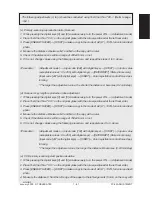
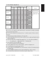
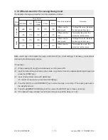
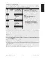
(7) Input a value according to the supplementary data sheet and press either [SET] or [INTERRUPT] key.
(8) Turn the power OFF.
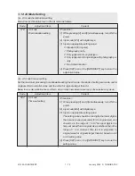
< Settings for developer bias >
(1) Turn the power ON while pressing [0] and [5] simultaneously.
(2) Input code [257] and press [START] key.
촞
The lower limit value for developer bias is displayed for each Y, M, C and K.
(3) Input sub-code (0: Y, 1: M, 2: C, 3: K) and press [START] key.
(4) Input a value according to the supplementary data sheet and press either [SET] or [INTERRUPT] key.
(5) Input code [258] and press [START] key.
촞
The upper limit value for developer bias is displayed for each Y, M, C and K.
(6) Input the sub-code (0: Y, 1: M, 2: C, 3: K) and press [START] key.
(7) Input a value according to the supplementary data sheet and press either [SET] or [INTERRUPT] key.
(8) Turn the power OFF.
1.14.3 Settings after replacing transfer transformer
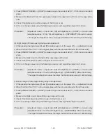
After replacing a transfer transformer, input the data shown on the supplementary data sheet (transfer
bias) according to the procedure below without fail.
<Settings for transfer roller bias>
(1) Turn the power ON while pressing [0] and [5] simultaneously.
(2) Input code [367] and press [START] key.
촞
The lower limit value for transfer bias is displayed for each Y, M, C and K.
(3) Input the sub-code (0: Y, 1: M, 2: C, 3: K) and press [START] key.
(4) Input a value according to the supplementary data sheet, and press either [SET] or [INTERRUPT]
key.
* Perform the operation in (3) and (4) for each of Y, M, C and K.
(5) Input code [368] and press [START] key.
촞
The upper limit value for transfer bias is displayed for each Y, M, C and K.
(6) Input the sub-code (0: Y, 1: M, 2: C, 3: K) and press [START] key.
(7) Input a value according to the supplementary data sheet, and press either [SET] or [INTERRUPT]
key.
* Perform the operation in (6) and (7) for each of Y, M, C and K.
(8) Turn the power OFF.
Summary of Contents for FC22
Page 115: ...FC 22 PREVENTIVE MAINTENANCE 2 8 January 2000 TOSHIBA TEC Front side drive system 47 20 ...
Page 121: ......
Page 235: ...January 2000 TOSHIBA TEC 5 29 FC 22 FIRMWARE UPDATING ...
Page 237: ...FC 22 SERVICE HANDBOOK 6 WIRE HARNESS CONNECTION DIAGRAMS 6 2 DC Wire Harness ...
Page 238: ...FC 22 WIREHARNESS CONNECTION DIAGRAMS 6 3 January 20000 TOSHIBA TEC ...

