


January 2000 © TOSHIBA TEC
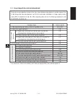
1 - 59
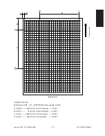
FC-22 ADJUSTMENT
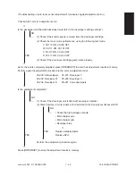
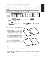
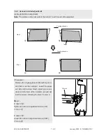
Step 2
In case of
C
:
Tighten the mirror-1 adjustment screw (CW).
→
Normal image
In case of
D
:
Loosen the mirror-1 adjustment screw (CCW).
→
Normal image
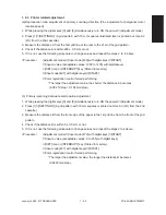
Note: After the image distortion adjustment, when
the adjustment screws of the mirror 1 and 2
are turned, lock the adjustment screws us-
ing the screw locking agent “BOND-1324”.
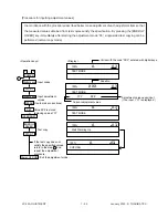
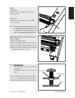
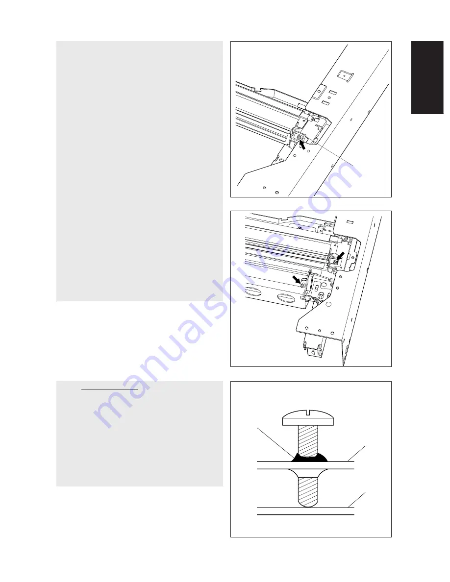
Mirror-1
[Application Method of the Adhesive for the
Screw Locking]
(1) Adjust the image distortion.
(2) Remove the original glass and the indicator unit.
(3) Move the carriage 1 toward the paper exit side.
(4) Apply the adhesive (BOND-1324) to the adjust-
ment screws of carriage 1 and 2.
Mirror
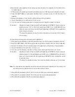
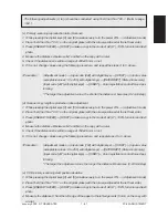
Note: Application Method
*Apply good quantity of the adhesive to the “Ap-
plication area”.
*The adhesive needs 12 hours to harden com-
pletely.
(5) Confirm that there is no dust or stain on the mir-
ror 1, 2 or 3 or the shading correction plate.
(6) Install the indicator unit and the original glass.
Application area
Carriage frame
Summary of Contents for FC22
Page 115: ...FC 22 PREVENTIVE MAINTENANCE 2 8 January 2000 TOSHIBA TEC Front side drive system 47 20 ...
Page 121: ......
Page 235: ...January 2000 TOSHIBA TEC 5 29 FC 22 FIRMWARE UPDATING ...
Page 237: ...FC 22 SERVICE HANDBOOK 6 WIRE HARNESS CONNECTION DIAGRAMS 6 2 DC Wire Harness ...
Page 238: ...FC 22 WIREHARNESS CONNECTION DIAGRAMS 6 3 January 20000 TOSHIBA TEC ...


