FC-22 TROUBLESHOOTING
4 - 30
January 2000 © TOSHIBA TEC
4.1.13
Fuser unit related service call
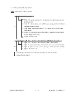
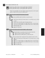
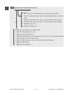
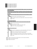
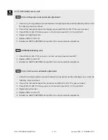
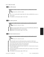
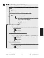
C41
Thermistor or heater abnormal when warming-up is started
*
To avoid any safety hazards, be sure to unplug the power cable before proceeding to check items
in 1. and 2. below.
*
Be sure that the fuser unit is set in place securely.
1. Checking the thermistors
(1) Is any thermistor connector disconnected?
(2) Are the thermistors (upper and lower, center and rear) in proper contact with the upper and lower
fuser rollers?
(3) Is the harness for the thermistors (upper and lower, center and rear) open-circuited?
2. Checking the fuser lamps and SSR
(1) Check if the upper or lower fuser lamp is open-circuited.
(2) Check if the upper or lower fuser lamp connector is disconnected.
(3) Check if the thermostat is blown out.
(4) Check if the upper fuser roller or lower fuser roller SSR connector is disconnected.
(5) Check if the AC harness is open-circuited.
(6) Check if SSR or the switching power supply is broken.
3. Checking the LGC board
(1) Check the LGC board if the connector J122 is disconnected.
(2) Check the LGC board for any abnormal condition, such as an open- or short-circuited conductor
pattern.
(3) Replace the LGC board.
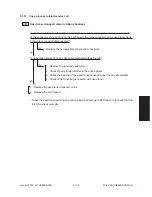
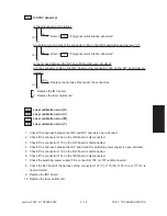
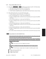
4. Clearing the status counter
After completing the repair of what caused the problem C41 , proceed to do the following:
(1) While pressing [0] and [8] simultaneously, turn ON the power.
(2) Enter [700] with digital keys, then press the START key.
(3) Rewrite [1] or [2] displayed on the status counter to [0], then press the INTERRUPT key ( C41
cleared).
(4) Turn OFF the power and then back it ON again, and make sure that the copier gets ready normally.
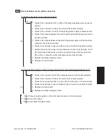
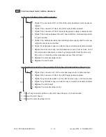
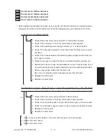
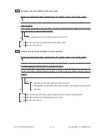
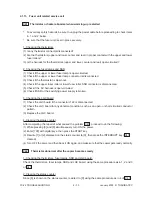
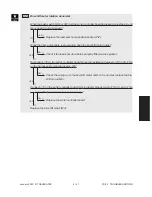
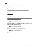
C42
Thermistor abnormal after the copier becomes ready
1. Checking the thermistors, fuser lamps, SSR and LGC board.
Check the thermistors, fuser lamps, SSR and LGC board, using the same procedure as in 1, 2 and 3
of C41 .
2. Clearing the status counter
Since [6] is shown on the status counter, rewrite it to [0] using the same procedure as in 4 of C41 .
Summary of Contents for FC22
Page 115: ...FC 22 PREVENTIVE MAINTENANCE 2 8 January 2000 TOSHIBA TEC Front side drive system 47 20 ...
Page 121: ......
Page 235: ...January 2000 TOSHIBA TEC 5 29 FC 22 FIRMWARE UPDATING ...
Page 237: ...FC 22 SERVICE HANDBOOK 6 WIRE HARNESS CONNECTION DIAGRAMS 6 2 DC Wire Harness ...
Page 238: ...FC 22 WIREHARNESS CONNECTION DIAGRAMS 6 3 January 20000 TOSHIBA TEC ...

