


247
(24) Execute Parameter Initialize by following the steps below.
a. Press “
FUNCTION
” and then “
7
” keys.
b. Press “
MONITOR
” four times, then press “
∗
(TONE)
” to enter the “
SERVICE MODE
”.
c. Press “
6
“ key or “V”, ”/\” arrow keys to enter “
6 RAM INITIALIZE
“.
d. Press “V”, ”
/\
” arrow keys to enter "
PARAMETER INITIALIZE
".
e. Press “
START
” key. Wait approximately 10-20 seconds. unit displays “
COMPLETED
”, then the unit
will return to Service Mode.
f. Turn the Power Switch on the Rear side of the machine to the
OFF
and back to the
ON
position to
enable the parameter settings.
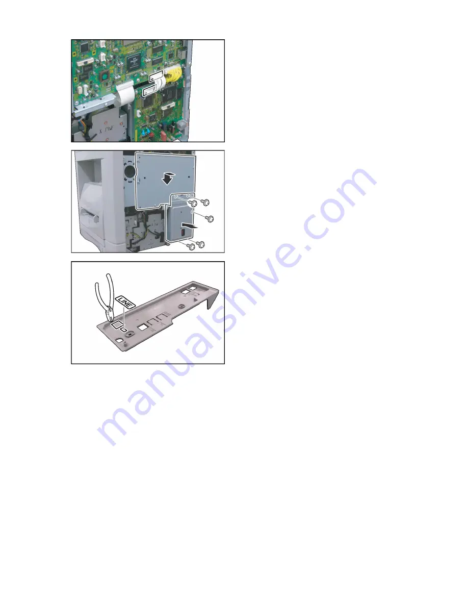
(14) Connect one end of the
G3B Harness
to CN510
on the SC PC Board.
(15) Connect other end of the
G3B Harness
to
CN363 on the G3B PC Board.
Caution:
Ensure that the
Black Wire
is on the
Left Side
,
and that it connects to
Pin 1
of the female
connector as illustrated.
(16) Reinstall the
SC Cover
and secure it with 5
Screws.
(17) Install the
Fax Cover
.
(18) Secure the
Fax Cover
with 5 Screws.
(19) Remove the
Protective Tab
covering the G3
Communication Port on the Rear Cover.
(20) Attach the
G3 Line Label
to the Rear Cover as
illustrated.
(21) Proceed with the installation of other options.
If finished, reinstall the SD Memory Card if it was
removed, and all Harnesses and Covers.
(22) Plug the
AC Power Cord
and turn the Power
Switch on the Rear Side of the machine to the
ON position.
(23) Reconnect the
Telephone Line Cable
if it was
disconnected.
Summary of Contents for e-STUDIO190F
Page 5: ...5 ...
Page 21: ...21 1 2 Control Panel For Americas e STUDIO190F ...
Page 119: ...119 Sensor and Switch Location ...
Page 185: ...185 6 3 Printer Receive Mechanism 6 3 1 Component Layout and Paper Path ...
Page 234: ...234 7 Installation Refer to Quick Guide For Facsimile and Copy Functions ...
Page 297: ...297 memo ...
Page 299: ...299 memo ...


