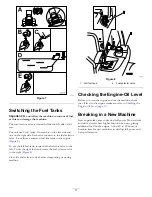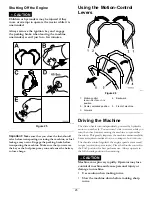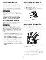
Stopping the Machine
To stop the machine, move the traction control levers to the
N
EUTRAL
position and then to the N
EUTRAL
-
LOCK
position,
disengage the blade-control switch (PTO), and turn the
ignition key to the O
FF
position.
Engage the parking brake when you leave the machine.
Remember to remove the key from the ignition switch.
CAUTION
Children or bystanders may be injured if they
move or attempt to operate the machine while it is
unattended.
Always remove the ignition key and engage
the parking brake when leaving the machine
unattended, even if just for a few minutes.
Using the Side Discharge
The mower has a hinged grass deflector that disperses
clippings to the side and down toward the turf.
DANGER
Without a grass deflector, discharge cover, or a
complete grass-catcher assembly mounted in
place, you and others are exposed to blade contact
and thrown debris. Contact with rotating mower
blade(s) and thrown debris will cause injury or
death.
•
Never remove the grass deflector from the mower
because the grass deflector routes material down
toward the turf. If the grass deflector is ever
damaged, replace it immediately.
•
Never put your hands or feet under the mower.
•
Never try to clear the discharge area or mower
blades unless you move the blade-control switch
(PTO) to the O
FF
position, rotate the ignition
key to the O
FF
position, and remove the key.
•
Make sure that the grass deflector is in the down
position.
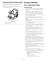
Using the Lift-Assist Lever
The lift assist lever is used along with the height-of-cut lever
for raising the mower deck. This allows for easier raising of
the mower deck.
1.
Place your foot onto lift-assist lever.
2.
Press on the lift-assist lever while pulling up on the
height-of-cut lever (
g001807
Figure 29
1.
Lift-assist lever
Adjusting the Height of Cut
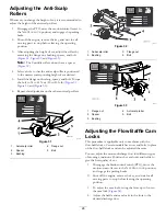
Adjust the height of cut from 38 to 127 mm (1-1/2 to 5
inches) in 6 mm (1/4 inch) increments by moving the clevis
pin into different hole locations.
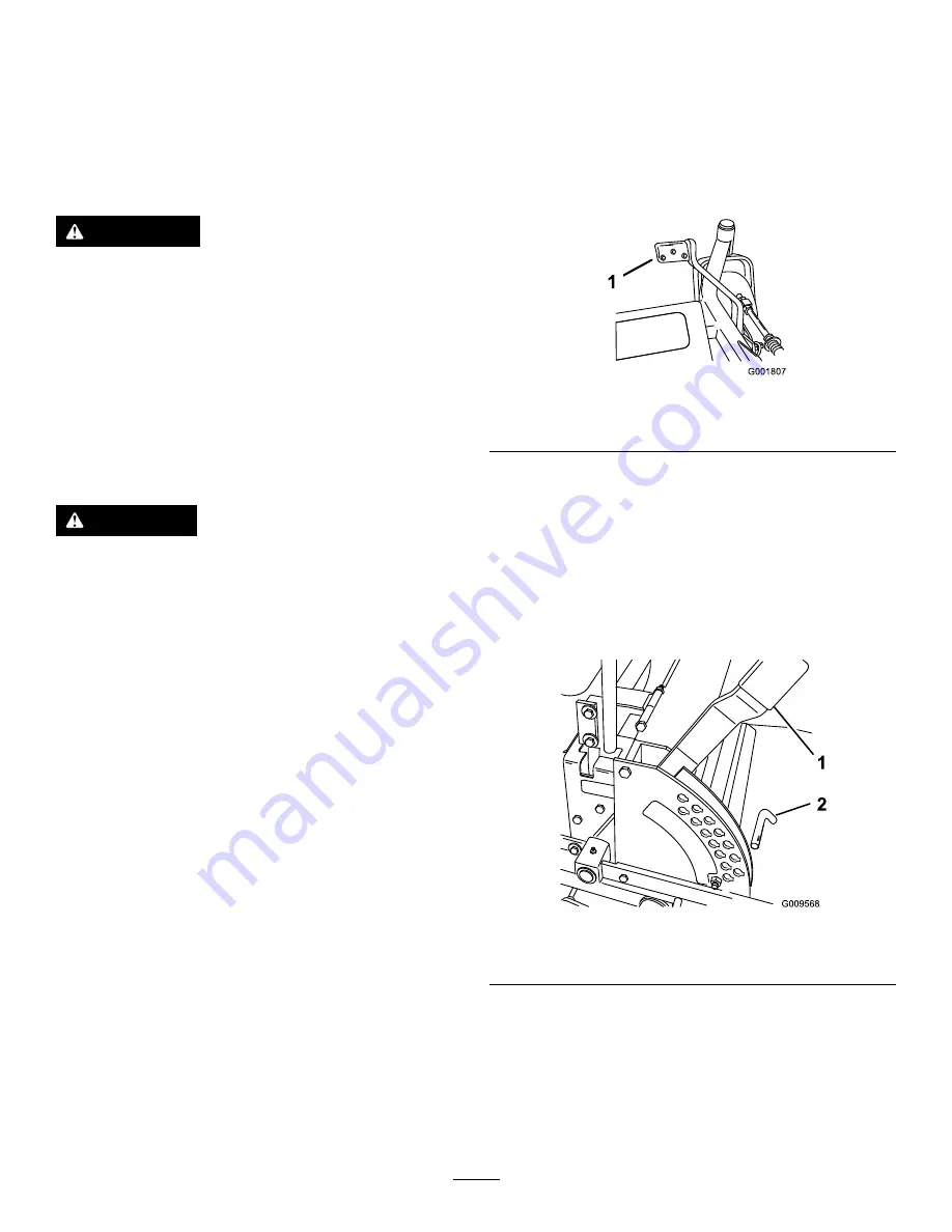
1.
Raise the height-of-cut lever to the T
RANSPORT
position (also the 127 mm (5 inches) cutting-height
position) (
).
g009568
Figure 30
1.
Height-of-cut lever
2.
Pin
2.
To adjust, remove the pin from the height-of-cut
bracket (
).
3.
Select a hole in the height-of-cut bracket corresponding
to the height of cut desired, and insert the pin (
4.
Move the lever to the selected height.
27
Summary of Contents for Z593-D Z Master 74264TE
Page 75: ...Schematics g012068 g012068 Wire Diagram Rev A 75 ...
Page 76: ...Notes ...
Page 77: ...Notes ...
Page 78: ...Notes ...


