


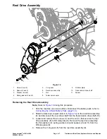
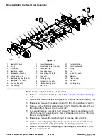

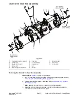


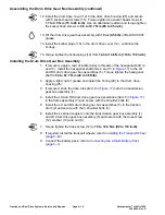

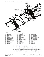
Assembling the Drum Drive Gear Box Assembly
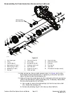
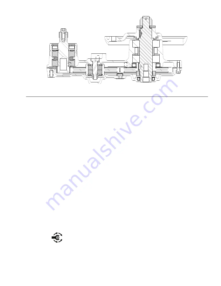
g263151
Figure 19
1. Install the ball bearings (23), wave washer (24) and spur gear (21) to the
drum drive housing (25).
Note:
The outer diameter and inner diameter of the ball bearings (23) must
be slip fit.
2. Install the retaining ring (26) to the spur gear (21). Apply a light coat of oil to
the oil seal (27). Install the oil seal (27) and retaining ring (28) to the drum
driving housing (25).
3. Use a press to install the ball bearings (19) to the spur gear (20). Install the
retaining rings (18) to spur gear (20).
Note:
The inner diameter of the ball bearing (19) must be slip fit.
4. Apply a light coat of grease and install the O-ring (32) to the bearing pin (31).
Install the bearing spacer (34), spur gear (20) onto the drum drive housing
(25) and secure with the bearing pin (31) and nut (17).
5. Install the ball bearings (6), bearing spacer (7), spring washer (9) and drum
drive shaft (5) to the drum drive housing (25).
Note:
The outer diameter and inner diameter of the ball bearings (6) must
be slip fit.
6. Install the V-ring seal (4) onto the drum outer hub (3). Install the key (30) to
the drum drive shaft (5) and apply anti-seize lubricant at the top of the key.
Slide the drum outer hub (3) to the drum drive shaft (5) and secure with
the washer (2) and nut (1).
7. Install the oil seal (10) into the drum drive housing (25). Install the key (30)
to the drum drive shaft (5) and apply anti-seize lubricant at the top of the
key. Slide the spur gear (11) to the drum drive shaft (5) and secure with
the nut (12).
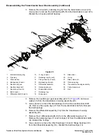
8. Torque tighten the nut (17) from
36.5 to 44.7 N·m (27 to 33 ft-lb)
.
9. Hold the nut (12) and torque tighten the nut (1) from
74.5 to 88 N·m (55
to 65 ft-lb)
.
10. If removed, install the oil seal (13) to the drum drive cover (14).
11. Install the gasket (8) to the drum drive housing.
Greensmaster
®
e1021/e1026
Page 4–15
Traction and Reel Drive Systems: Service and Repairs
20246SL Rev A
Summary of Contents for 04831
Page 4: ...NOTES NOTES Page 4 Greensmaster e1021 e1026 20246SL Rev A ...
Page 6: ...g340650 Figure 1 Model 04831 shown Preface Page 6 Greensmaster e1021 e1026 20246SL Rev A ...
Page 14: ...Safety Safety and Instructional Decals Page 1 6 Greensmaster e1021 e1026 20246SL Rev A ...
Page 136: ...Electrical System Service and Repairs Page 5 56 Greensmaster e1021 e1026 20246SL Rev A ...
Page 216: ......


