Disassembling the Transmission Gear Box Assembly (continued)
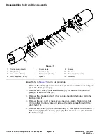
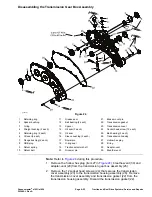
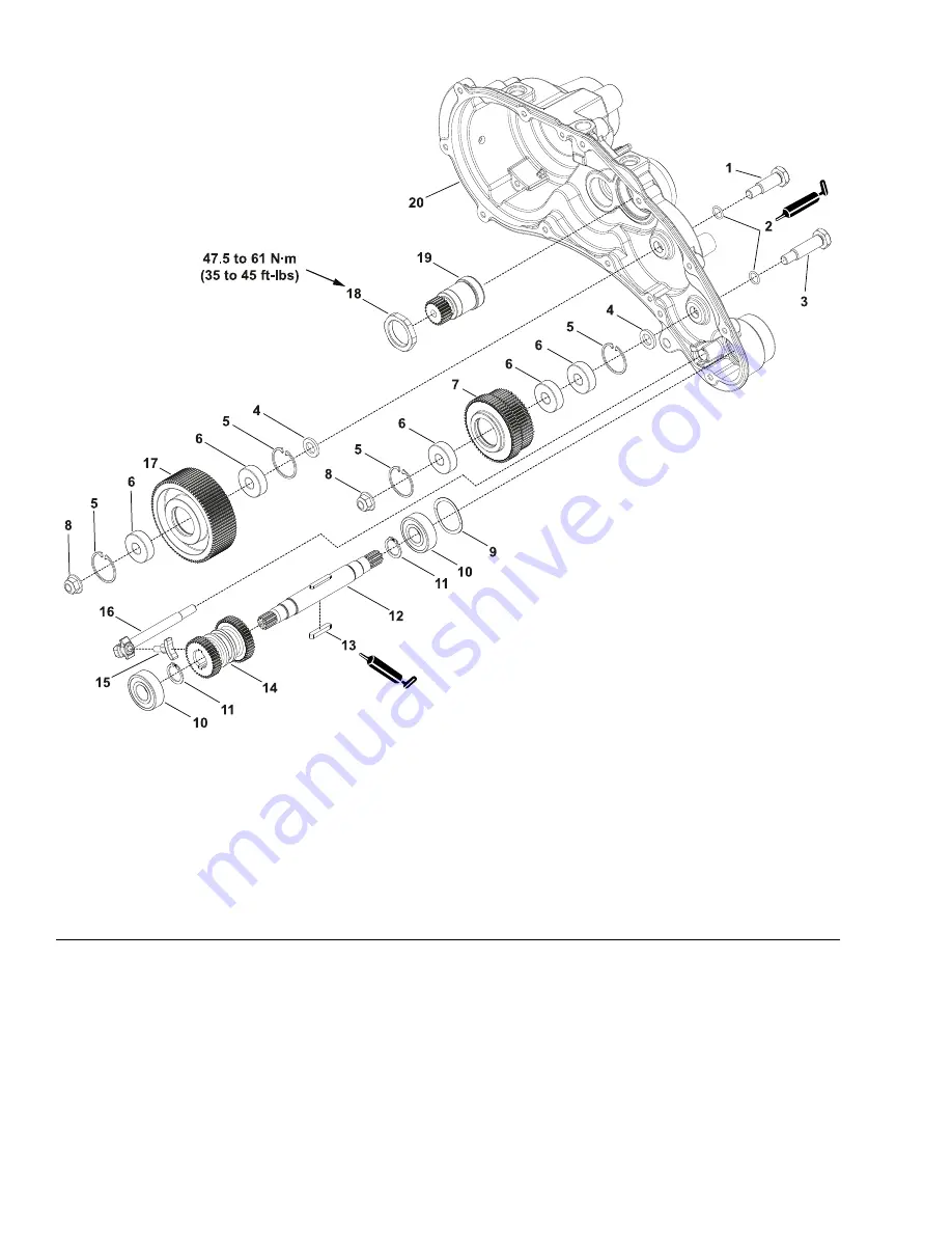
g339789
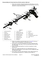
Figure 26
1.
Short bearing pin
8.
Flange nut (2 each)
15.
Reel clutch shoe
2.
O-ring
9.
Wave spring
16.
Reel clutch actuator
3.
Long bearing pin
10.
Ball bearing (2 each)
17.
Spur gear
4.
Bearing spacer (2 each)
11.
Retaining ring (2 each)
18.
Thin lock nut
5.
Retaining ring (4 each)
12.
Reel drive shaft
19.
Input shaft
6.
Ball bearing (5 each)
13.
Square key (2 each)
20.
Transmission housing assembly
7.
Spur gear
14.
Slider spur gear
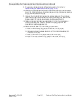
14. Slide and remove the reel clutch actuator (item 16 in
) from the
transmission housing assembly (20). If necessary, remove the reel clutch
shoe (15) from the reel clutch actuator (16).
15. Remove the reel drive shaft assembly (12), ball bearing (10) and wave spring
(9) from the transmission housing assembly (20). If necessary, disassemble
the drive shaft assembly (12) as follows:
A. Use a press to remove the ball bearings (10) from the reel drive shaft
(12). Discard the bearings (10).
B. Remove the retaining ring (11) from the reel drive shaft (12).
Traction and Reel Drive Systems: Service and Repairs
Page 4–26
Greensmaster
®
e1021/e1026
20246SL Rev A
Summary of Contents for 04831
Page 4: ...NOTES NOTES Page 4 Greensmaster e1021 e1026 20246SL Rev A ...
Page 6: ...g340650 Figure 1 Model 04831 shown Preface Page 6 Greensmaster e1021 e1026 20246SL Rev A ...
Page 14: ...Safety Safety and Instructional Decals Page 1 6 Greensmaster e1021 e1026 20246SL Rev A ...
Page 136: ...Electrical System Service and Repairs Page 5 56 Greensmaster e1021 e1026 20246SL Rev A ...
Page 216: ......

