Testing the Throttle and Clutch Bail Potentiometers (continued)
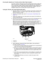
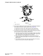
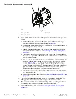
6. After you complete the testing, secure the potentiometers to the machine
(
). Secure the wire harness connector to the potentiometer. Secure
the handle cover to the handle.
Note:
When re-installing the potentiometers, a minimum voltage reading of
0.5V for proper function is required. This can be read in the InfoCenter. The
adjustment is completed by rotating the potentiometers in the mounting slots
until the minimum voltage at the neutral position is achieved.
7. Connect the battery pack; refer to
Connecting the Lithium Battery Pack
(page 5–3)
.
Greensmaster
®
e1021/e1026
Page 5–35
Electrical System: Testing the Electrical Components
20246SL Rev A
Summary of Contents for 04831
Page 4: ...NOTES NOTES Page 4 Greensmaster e1021 e1026 20246SL Rev A ...
Page 6: ...g340650 Figure 1 Model 04831 shown Preface Page 6 Greensmaster e1021 e1026 20246SL Rev A ...
Page 14: ...Safety Safety and Instructional Decals Page 1 6 Greensmaster e1021 e1026 20246SL Rev A ...
Page 136: ...Electrical System Service and Repairs Page 5 56 Greensmaster e1021 e1026 20246SL Rev A ...
Page 216: ......

