


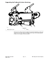


Assembling the Handle Assembly (continued)
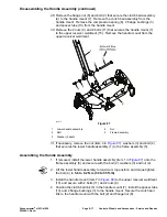
5. Position the compression spring (6), spacer tube (13) and 2 bushings (3) into
the handle mount (7). Install the clutch bail assembly (4) to the handle mount
(7) and secure with the bolt (2) and flange nut (8).
6. If removed, install the LH and RH bail brackets (1 and 15) to the handle
(16) with the 2 screws (14).
7. Install the clutch bail assembly (4) to the handle (16). Secure the handle to
the handle mount (7) with the 2 bolts (17) and 2 nuts (8).
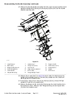
8. Position the spring spacer (Item 24 in
) and handle torsion spring
(23) into the handle adjuster assembly (22). Install the handle adjuster
assembly to the upper receiver weldment (8) with the clevis pin (14), bearing
washer (15) and cotter pin (18).
9. If removed, install the lift assist handle (27) to the upper receiver weldment
(8) and secure with the bolts (16 and 11).
10. Slide the upper receiver weldment (8) in to the lower handle assembly (19)
and secure with the bolt (29) and flange nut (9).
Note:
Do not tighten bolt and nut. Install the nut to engage locking feature.
The upper receiver weldment (8) must be free to slide.
11. Reposition the wire harness.
12. If removed, install the flange bushings (5), bolt (12) and flange nut (13) into
the brake lever (6).
13. Position the brake lever (6) to the upper receiver weldment (8) and secure
with the shoulder screw (4) and flange nut (7).
14. Install the InfoCenter mount (item 4 in
) onto the handle and secure
with the 4 screws (1).
15. Install the wire harness.
16. If removed, install the flange bushings (item 31 in
) inside the
throttle arm (1).
17. If removed, slide the throttle lever (34) onto the throttle arm (1) and secure
with bolt (32).
18. Torque tighten the bolt from
2.2 to 3.4 N·m (20 to 30 in-lb)
.
19. Install the throttle arm (1) to the handle assembly (3) and secure with bolt
(30), washer (2) and nut (20).
20. Install the bolt (21) and 2 flange nuts (7) to the upper receiver weldment (8).
Ensure that the head of the bolt is resting the on throttle arm (1).
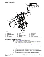
21. Install the brake latch shaft; refer to
Assembling the Brake Latch Shaft (page
.
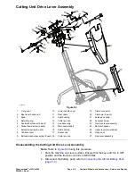
22. Install the clutch and reel drive lever assembly; refer to
Cutting Unit Drive Lever Assembly (page 6–10)
.
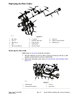
23. Install the reel cable; refer to
Installing the Reel Cable (page 6–8)
.
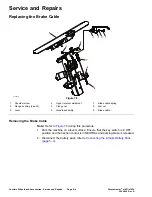
24. Install the brake cable; refer to
Installing the Brake Cable (page 6–5)
.
25. Install the throttle cable (27).
26. Adjust the traction bail proximity sensor; refer to
Proximity Sensor (page 5–20)
.
27. Install the bottom control cover and re-position the wire harness to the upper
receiver weldment and secure with the 2 screw and washer assemblies, 2
bolts and 2 nuts.
Controls, Wheels and Accessories : Service and Repairs
Page 6–18
Greensmaster
®
e1021/e1026
20246SL Rev A
Summary of Contents for 04831
Page 4: ...NOTES NOTES Page 4 Greensmaster e1021 e1026 20246SL Rev A ...
Page 6: ...g340650 Figure 1 Model 04831 shown Preface Page 6 Greensmaster e1021 e1026 20246SL Rev A ...
Page 14: ...Safety Safety and Instructional Decals Page 1 6 Greensmaster e1021 e1026 20246SL Rev A ...
Page 136: ...Electrical System Service and Repairs Page 5 56 Greensmaster e1021 e1026 20246SL Rev A ...
Page 216: ......