


Greensmaster 3300/3400
Page 6 -- 42
Electrical System
Main Power, Charge Circuit (Greensmaster 3300), Glow (Greensmaster 3400) and Fan
(Greensmaster 3400) Relays
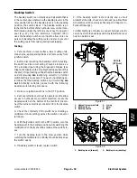
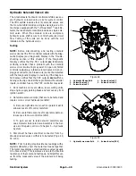
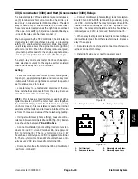
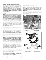
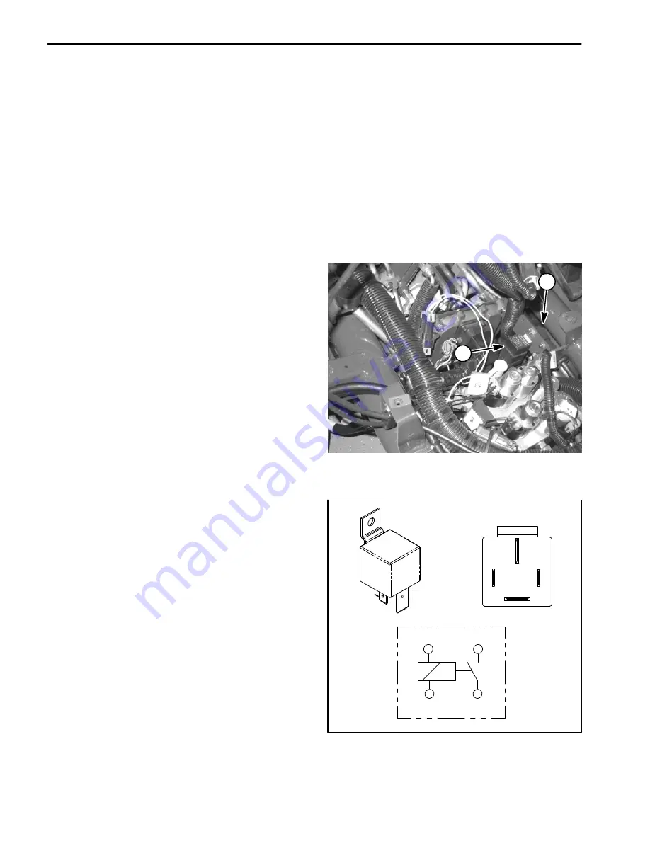
The Greensmaster TriFlex electrical system includes
several identical, four (4) terminal relays for current con-
trol. The relays are located under the right side cover
next to the operator seat (Fig. 52). Relays can be identi-
fied by a tag near the relay wire harness connector.
The main power relay provides electrical current to the
fuse blocks when energized by the ignition switch in the
RUN or START position. The main power relay is used
on both Greensmaster 3300 and 3400 machines.
The charge circuit relay on Greensmaster 3300 ma-
chines provides a current path for alternator output to
reach the machine’s electrical system. The charge cir-
cuit relay is energized by the Toro Electronic Controller
(TEC) when the ignition switch is in the RUN or START
position.
The glow relay on Greensmaster 3400 machines pro-
vides electrical current to the engine glow plugs when
energized by the TEC controller.
The fan relay on Greensmaster 3400 machines pro-
vides electrical current to the engine cooling fan when
energized by the TEC controller. The fan relay is ener-
gized when engine coolant temperature reaches
approximately 185
o
F (85
o
C).
The charge circuit, glow and fan relays along with their
circuit wiring
should
be tested as a TEC controller out-
put with the Diagnostic Display before disconnecting
and testing the relay (see Diagnostic Display in the Trou-
bleshooting section of this chapter).
Testing
1. Park machine on a level surface, lower cutting units,
stop engine, apply parking brake and remove key from
ignition switch. Remove right side cover next to operator
seat to allow access to relays.
2. Make sure ignition switch is in the OFF position. Lo-
cate the relay to be tested and disconnect wire harness
electrical connector from relay. Remove relay from
bracket for easier testing.
NOTE:
Prior to taking small resistance readings with a
digital multimeter, short the meter test leads together.
The meter will display a small resistance value (usually
0.5 ohms or less). This resistance is due to the internal
resistance of the meter and test leads. Subtract this val-
ue from the measured value of the relay being testing.
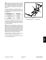
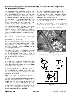
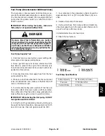
3. Measure coil resistance between terminals 85 and
86 with a multimeter (ohms setting) (Fig. 53). Resist-
ance should be approximately
72 ohms
.
4. Connect multimeter (ohms setting) leads to relay ter-
minals 30 and 87. Ground terminal 86 and apply +12
VDC to terminal 85. The relay should make and break
continuity between terminals 30 and 87 as +12 VDC is
applied and removed from terminal 85.
5. Disconnect voltage and leads from the relay termi-
nals. Replace relay if necessary.
6. After testing is completed, secure relay to bracket
and connect wire harness electrical connector to relay.
7. Install right side cover next to operator seat.
1. Relay (4 terminal)
2. Relay (5 terminal)
Figure 52
2
1
Figure 53
86
87
85
30
85
86
87
30
Summary of Contents for 04510 Greensmaster 3300 TriFlex
Page 2: ...Greensmaster 3300 3400 This page is intentionally blank ...
Page 4: ...Greensmaster 3300 3400 This page is intentionally blank ...
Page 6: ...Greensmaster 3300 3400 This page is intentionally blank ...
Page 24: ...Greensmaster 3300 Page 3 6 Gasoline Engine This page is intentionally blank ...
Page 38: ...Greensmaster 3400 Page 4 4 Diesel Engine This page is intentionally blank ...
Page 54: ...Greensmaster 3300 3400 Hydraulic System Page 5 2 This page is intentionally blank ...
Page 170: ...Greensmaster 3300 3400 Hydraulic System Page 5 118 This page is intentionally blank ...
Page 172: ...Greensmaster 3300 3400 Page 6 2 Electrical System This page is intentionally blank ...
Page 230: ...Greensmaster 3300 3400 Page 6 60 Electrical System This page is intentionally blank ...
Page 303: ...Greensmaster 3300 3400 Groomer Page 9 13 This page is intentionally blank Groomer ...
Page 318: ...Greensmaster 3300 3400 Page 10 2 Foldout Drawings This page is intentionally blank ...
Page 332: ...Page 10 16 This page is intentionally blank ...


