


Greensmaster 3300/3400
Page 6 -- 12
Electrical System
Diagnostic Display
Your Greensmaster is equipped with a Toro Electronic
Controller (TEC) which controls machine electrical func-
tions. The controller monitors various input switches
(e.g. ignition switch, seat switch, etc.) and energizes
outputs to actuate solenoids or relays for the requested
machine function.
For the controller to properly control the machine, each
of the input switches, output solenoids and relays must
be connected and functioning properly.
The Diagnostic Display (see Special Tools in this chap-
ter) is a tool to help the technician verify correct electrical
functions of the machine.
IMPORTANT: The Diagnostic Display must not be
left connected to the machine. It is not designed to
withstand the environment of the machine’s every
day use. When use of the Diagnostic Display is com-
pleted, disconnect it from the machine and recon-
nect loopback connector to harness connector. The
machine will not operate without the loopback con-
nector installed on the harness. Store the Diagnos-
tic Display in a dry, secure, indoor location, not on
machine.
CAUTION
The interlock switches are for the protection of
the operator and bystanders and to ensure cor-
rect operation of the machine. Do not bypass or
disconnect interlock switches. Check the opera-
tion of the interlock switches daily for proper op-
eration. Replace any malfunctioning switches
before operating the machine.
Verify Diagnostic Display Input Functions
1. Park machine on a level surface, lower the cutting
units, engage the parking brake and stop the engine.
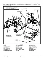
2. Remove right side cover next to operator seat to al-
low access to the TEC controller. Locate wire harness
and connectors near TEC controller. Carefully unplug
loopback connector from harness connector (Fig. 14).
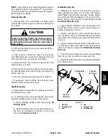
3. Connect the Diagnostic Display connector to the har-
ness connector. Make sure correct overlay decal is posi-
tioned on the Diagnostic Display (Fig. 15).
4. Turn the ignition switch to the RUN position, but do
not start machine.
NOTE:
The
red
text on the overlay decal refers to con-
troller inputs and the
green
text refers to outputs.
1. TEC controller
2. Loopback connector
Figure 14
1
2
Figure 15
OVERLAY
DIAGNOSTIC
DISPLAY
115--8227
Summary of Contents for 04510 Greensmaster 3300 TriFlex
Page 2: ...Greensmaster 3300 3400 This page is intentionally blank ...
Page 4: ...Greensmaster 3300 3400 This page is intentionally blank ...
Page 6: ...Greensmaster 3300 3400 This page is intentionally blank ...
Page 24: ...Greensmaster 3300 Page 3 6 Gasoline Engine This page is intentionally blank ...
Page 38: ...Greensmaster 3400 Page 4 4 Diesel Engine This page is intentionally blank ...
Page 54: ...Greensmaster 3300 3400 Hydraulic System Page 5 2 This page is intentionally blank ...
Page 170: ...Greensmaster 3300 3400 Hydraulic System Page 5 118 This page is intentionally blank ...
Page 172: ...Greensmaster 3300 3400 Page 6 2 Electrical System This page is intentionally blank ...
Page 230: ...Greensmaster 3300 3400 Page 6 60 Electrical System This page is intentionally blank ...
Page 303: ...Greensmaster 3300 3400 Groomer Page 9 13 This page is intentionally blank Groomer ...
Page 318: ...Greensmaster 3300 3400 Page 10 2 Foldout Drawings This page is intentionally blank ...
Page 332: ...Page 10 16 This page is intentionally blank ...


