


Greensmaster 3300/3400
Page 6 -- 39
Electrical System
Backlap Switch
The backlap switch is a normally open ball switch that is
in the normal, open state when the backlap lever is in the
mow position. When the backlap lever is in the backlap
position, the switch closes. The backlap switch is at-
tached to the bottom of the hydraulic mow control man-
ifold located under the left side cover next to operator
seat (Fig. 47). The Toro Electronic Controller (TEC)
uses the backlap switch as an input to allow only one
person to backlap the cutting reels and also to prevent
the cutting reels from raising during backlapping.
Testing
1. Park machine on level surface, lower cutting units,
stop engine, apply parking brake and remove key from
ignition switch.
2. Before disconnecting the backlap switch for testing,
the switch and its circuit wiring should be tested as a
TEC electrical input using the Diagnostic Display (see
Diagnostic Display in the Troubleshooting section of this
chapter). If input testing verifies that the backlap switch
and circuit wiring
are
functioning correctly, no further
switch testing is necessary. If, however, input testing de-
termines that the backlap switch and circuit wiring
are
not
functioning correctly, proceed with the following
backlap switch testing procedure.
3. Make sure ignition switch is in the OFF position.
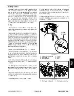
4. Remove left side cover next to operator seat to allow
access to hydraulic mow control manifold. Locate the
backlap switch on the bottom of the manifold. Discon-
nect the harness electrical connector from the backlap
switch.
5. Check the continuity of the switch by connecting a
multimeter (ohms setting) across the switch connector
terminals.
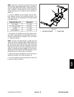
6. With the ignition switch in the OFF position, turn the
backlap lever to the backlap position while watching the
multimeter. Continuity should be made as the switch clo-
ses.
7. Turn the backlap lever to the mow position while
watching the multimeter. Continuity should be broken as
the switch opens.
8. If backlap switch is faulty, replace switch.
9. If the backlap switch tests correctly and a circuit
problem still exists, check wire harness (see Electrical
Schematic and Wire Harness Drawings in Chapter 10 --
Foldout Drawings).
10.After testing is completed, connect harness electri-
cal connector to the backlap switch. Install left side cover
next to operator seat.
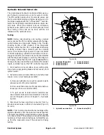
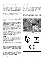
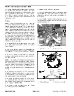
1. Hydraulic mow manifold
2. Backlap lever
3. Backlap switch
4. O--ring
5. Shim
6. Ball
Figure 47
20 ft--lb
(27 N--m)
3
4
5
1
2
6
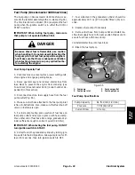
1. Backlap lever (forward)
2. Backlap lever (backlap)
Figure 48
2
1
Electrical System
Summary of Contents for 04510 Greensmaster 3300 TriFlex
Page 2: ...Greensmaster 3300 3400 This page is intentionally blank ...
Page 4: ...Greensmaster 3300 3400 This page is intentionally blank ...
Page 6: ...Greensmaster 3300 3400 This page is intentionally blank ...
Page 24: ...Greensmaster 3300 Page 3 6 Gasoline Engine This page is intentionally blank ...
Page 38: ...Greensmaster 3400 Page 4 4 Diesel Engine This page is intentionally blank ...
Page 54: ...Greensmaster 3300 3400 Hydraulic System Page 5 2 This page is intentionally blank ...
Page 170: ...Greensmaster 3300 3400 Hydraulic System Page 5 118 This page is intentionally blank ...
Page 172: ...Greensmaster 3300 3400 Page 6 2 Electrical System This page is intentionally blank ...
Page 230: ...Greensmaster 3300 3400 Page 6 60 Electrical System This page is intentionally blank ...
Page 303: ...Greensmaster 3300 3400 Groomer Page 9 13 This page is intentionally blank Groomer ...
Page 318: ...Greensmaster 3300 3400 Page 10 2 Foldout Drawings This page is intentionally blank ...
Page 332: ...Page 10 16 This page is intentionally blank ...


