


Greensmaster 3300/3400
Hydraulic System
Page 5 -- 117
NOTE:
Greensmaster machines with gasoline engines
are equipped with the Turf Guardian
TM
Leak Detector
System. On machines with a diesel engine, the Leak De-
tector System is optional.
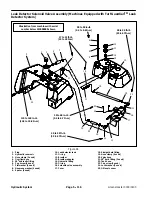
Removal (Fig. 84)
1. Park machine on a level surface, set brake, lower
cutting units and stop engine. Remove key from the igni-
tion switch.
CAUTION
Before continuing further, read and become fa-
miliar with General Precautions for Removing
and Installing Hydraulic System Components in
this section.
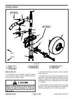
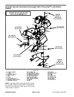
2. Remove leak detector tank (see Leak Detector Re-
moval in this section).
3. Clean junction of tank hose (item 22) at solenoid
valve fitting (item 21). Loosen hose clamp (item 19) and
disconnect tank hose at solenoid valve fitting.
4. Unplug machine wire harness connector from the
solenoid valve connector.
5. Remove two (2) cap screws (item 23) and lock wash-
ers (item 24) that secure solenoid valve assembly to hy-
draulic reservoir.
6. Remove solenoid valve assembly from machine.
7. If necessary, remove fittings from solenoid valve
manifold. Discard removed O--rings.
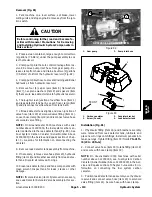
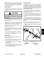
Manifold Service
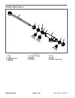
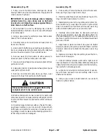
1. Disassemble solenoid valve manifold as needed us-
ing Figure 85 as a guide.
2. For cartridge valve service procedures, see Control
Manifold Cartridge Valve Service in this section.
A. When installing cartridge valve, torque valve
35
ft--lb (47 N--m)
.
B. When installing solenoid coil, apply a drop of Loc-
tite #242 (or equivalent) to threads of valve and
torque nut
10 in--lb (1.1 N--m)
.
Installation (Fig. 84)
1. If fittings were removed from solenoid valve man-
ifold, lubricate and place new O--rings onto fittings.
Install fittings into manifold openings. Tighten fittings
(see Hydraulic Fitting Installation in the General Infor-
mation section of this chapter). Torque fittings from
40
to 50 ft--lb (55 to 67 N--m)
.
2. Apply antiseize lubricant to the end threads of the
two (2) cap screws used to secure solenoid valve as-
sembly to hydraulic reservoir.
3. Position cover (item 17) and solenoid valve assem-
bly to hydraulic reservoir. Orientate the solenoid valve
assembly so the solenoid coil is closer to the front of the
reservoir.
4. Secure solenoid valve assembly to hydraulic reser-
voir with two (2) cap screws (item 23) and lock washers
(item 24). Torque cap screws from
30 to 60 in--lb (3.4 to
6.7 N--m)
.
5. Connect tank hose (item 22) to solenoid valve fitting
(item 21) and secure with hose clamp (item 19).
6. Install leak detector tank (see Leak Detector Installa-
tion in this section).
1. Manifold
2. Cartridge valve
3. Seal
4. Nut
5. Solenoid coil
6. Cartridge seal
Figure 85
2
3
4
1
5
6
10 in--lb
(1.1 N--m)
3
35 ft--lb
(47 N--m)
Loctite #242
Hydraulic System
Summary of Contents for 04510 Greensmaster 3300 TriFlex
Page 2: ...Greensmaster 3300 3400 This page is intentionally blank ...
Page 4: ...Greensmaster 3300 3400 This page is intentionally blank ...
Page 6: ...Greensmaster 3300 3400 This page is intentionally blank ...
Page 24: ...Greensmaster 3300 Page 3 6 Gasoline Engine This page is intentionally blank ...
Page 38: ...Greensmaster 3400 Page 4 4 Diesel Engine This page is intentionally blank ...
Page 54: ...Greensmaster 3300 3400 Hydraulic System Page 5 2 This page is intentionally blank ...
Page 170: ...Greensmaster 3300 3400 Hydraulic System Page 5 118 This page is intentionally blank ...
Page 172: ...Greensmaster 3300 3400 Page 6 2 Electrical System This page is intentionally blank ...
Page 230: ...Greensmaster 3300 3400 Page 6 60 Electrical System This page is intentionally blank ...
Page 303: ...Greensmaster 3300 3400 Groomer Page 9 13 This page is intentionally blank Groomer ...
Page 318: ...Greensmaster 3300 3400 Page 10 2 Foldout Drawings This page is intentionally blank ...
Page 332: ...Page 10 16 This page is intentionally blank ...


