


Greensmaster 3300/3400
Page 6 -- 37
Electrical System
Parking Brake Switch
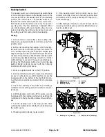
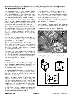
The parking brake switch is a normally open proximity
switch that mounts to the frame bracket used to attach
the parking brake lever assembly (Fig. 43). The sensing
plate for the brake switch is a tab on the parking brake
lever assembly. The Toro Electronic Controller (TEC)
monitors the operation of the parking brake switch.
When the parking brake is not applied, the tab on the
parking brake lever is positioned near the target end of
the parking brake switch so the switch is closed. The tab
on the parking brake lever is moved away from the
switch when the parking brake is applied causing the
switch to open.
Testing
1. Park machine on level surface, lower cutting units,
stop engine and remove key from ignition switch.
2. Before disconnecting the parking brake switch for
testing, the switch and its circuit wiring should be tested
as a TEC electrical input using the Diagnostic Display
(see Diagnostic Display in the Troubleshooting section
of this chapter). If input testing verifies that the brake
switch and circuit wiring
are
functioning correctly, no fur-
ther brake switch testing is necessary. If, however, input
testing determines that the brake switch and circuit wir-
ing
are not
functioning correctly, proceed with the fol-
lowing parking brake switch testing procedure.
3. Locate parking brake switch. Make sure that parking
brake is not applied.
4. Turn ignition switch to the RUN position (do not start
engine) and check LED on cable end of parking brake
switch. The switch LED
should be
illuminated when the
parking brake
is not
applied.
5. With the ignition switch still in the RUN position (do
not start engine), apply parking brake and check LED on
cable end of parking brake switch. The switch LED
should not be
illuminated when the parking brake
is
applied.
6. If the brake switch LED did not function correctly:
A. Make sure that parking brake switch is properly
adjusted (see Parking Brake Switch in the Adjust-
ments section of this chapter). If necessary, adjust
switch and return to step 4 above.
B. Make sure ignition switch is OFF and disconnect
the parking brake switch connector from the ma-
chine wire harness.
C. Using a multimeter, verify that the machine wire
harness connector terminal for black wire is closed
(continuity) to ground.
D. Turn ignition switch to the RUN position (do not
start engine) and verify with a multimeter that ma-
chine wire harness connector terminal for pink wire
has system voltage (12 VDC) present.
E. If black wire is closed to ground, pink wire has
system voltage present and switch LED did not func-
tion, replace parking brake switch. Adjust switch af-
ter installation (see Parking Brake Switch in the
Adjustments section of this chapter).
7. After brake switch testing is complete, make sure
that switch connector is plugged into machine wire har-
ness.
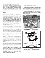
1. Brake lever
2. Parking brake switch
3. Switch LED location
4. Brake lever tab
Figure 43
2
1
3
4
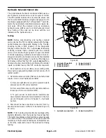
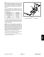
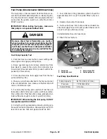
1. Parking brake switch
2. Parking brake lever
3. Jam nut (2 used)
4. Lock washer (2 used)
Figure 44
2
1
3
4
3
4
162 to 198 in--lb
(18.4 to 22.3 N--m)
Electrical System
Summary of Contents for 04510 Greensmaster 3300 TriFlex
Page 2: ...Greensmaster 3300 3400 This page is intentionally blank ...
Page 4: ...Greensmaster 3300 3400 This page is intentionally blank ...
Page 6: ...Greensmaster 3300 3400 This page is intentionally blank ...
Page 24: ...Greensmaster 3300 Page 3 6 Gasoline Engine This page is intentionally blank ...
Page 38: ...Greensmaster 3400 Page 4 4 Diesel Engine This page is intentionally blank ...
Page 54: ...Greensmaster 3300 3400 Hydraulic System Page 5 2 This page is intentionally blank ...
Page 170: ...Greensmaster 3300 3400 Hydraulic System Page 5 118 This page is intentionally blank ...
Page 172: ...Greensmaster 3300 3400 Page 6 2 Electrical System This page is intentionally blank ...
Page 230: ...Greensmaster 3300 3400 Page 6 60 Electrical System This page is intentionally blank ...
Page 303: ...Greensmaster 3300 3400 Groomer Page 9 13 This page is intentionally blank Groomer ...
Page 318: ...Greensmaster 3300 3400 Page 10 2 Foldout Drawings This page is intentionally blank ...
Page 332: ...Page 10 16 This page is intentionally blank ...


