


Greensmaster 3300/3400
Page 6 -- 29
Electrical System
Indicator Lights (Greensmaster 3400)
Charge Indicator Light
The charge indicator light should come on when the igni-
tion switch is in the RUN position with the engine not run-
ning. Also, it should illuminate with an improperly
operating charging circuit while the engine is running.
Engine Oil Pressure Light
The engine oil pressure light should come on when the
ignition switch is in the RUN position with the engine not
running. Also, it should illuminate with the engine run-
ning if the engine oil pressure drops to an unsafe level.
IMPORTANT: If the oil pressure indicator light is il-
luminated with the engine running, shut off the en-
gine immediately.
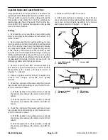
To test the oil pressure light and circuit wiring, ground the
wire attached to oil pressure switch located on the en-
gine near the oil filter. Turn ignition switch to the RUN
position; the engine oil pressure light should come on in-
dicating correct operation of the indicator light and cir-
cuit wiring.
High Temperature Warning Light
If the engine coolant temperature reaches 220
o
F
(105
o
C) (approximate), the high temperature warning
light will come on.
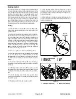
To test the high temperature warning light and circuit wir-
ing, turn ignition switch to the RUN position and ground
the wire attached to high temperature warning switch lo-
cated on the engine water pump housing (see High
Temperature Warning Switch in this section). The high
temperature warning light should illuminate when the
wire is grounded.
Glow Plug Indicator Light
The glow plug indicator light should come on when the
ignition switch is placed in the RUN position prior to plac-
ing the ignition switch in START. The light should stay lit
for approximately six (6) seconds while the ignition
switch is left in the RUN position.
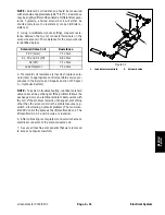
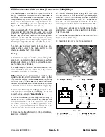
Testing Indicator Lights
1. Remove console cover from console assembly to
gain access to indicator lights (see Control Console Dis-
assembly in the Service and Repairs section of Chapter
7 -- Chassis).
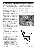
2. Apply 12 VDC to terminals 1A and 2A (Fig. 28) and
ground terminals 1B and 2B (Fig. 28).
3. Both indicator lights should illuminate.
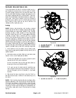
1. Charge indicator light
2. Oil pressure light
3. High temp warning light
4. Glow plug light
Figure 27
1
3
2
4
Figure 28
1. Charge indicator
2. Engine oil pressure
3. High temperature
4. Glow plug indicator
5. Indicator light front
6. Indicator light back
1A (+)
2A (+)
2B (--)
1B (--)
4
3
5
2
1
6
Electrical System
Summary of Contents for 04510 Greensmaster 3300 TriFlex
Page 2: ...Greensmaster 3300 3400 This page is intentionally blank ...
Page 4: ...Greensmaster 3300 3400 This page is intentionally blank ...
Page 6: ...Greensmaster 3300 3400 This page is intentionally blank ...
Page 24: ...Greensmaster 3300 Page 3 6 Gasoline Engine This page is intentionally blank ...
Page 38: ...Greensmaster 3400 Page 4 4 Diesel Engine This page is intentionally blank ...
Page 54: ...Greensmaster 3300 3400 Hydraulic System Page 5 2 This page is intentionally blank ...
Page 170: ...Greensmaster 3300 3400 Hydraulic System Page 5 118 This page is intentionally blank ...
Page 172: ...Greensmaster 3300 3400 Page 6 2 Electrical System This page is intentionally blank ...
Page 230: ...Greensmaster 3300 3400 Page 6 60 Electrical System This page is intentionally blank ...
Page 303: ...Greensmaster 3300 3400 Groomer Page 9 13 This page is intentionally blank Groomer ...
Page 318: ...Greensmaster 3300 3400 Page 10 2 Foldout Drawings This page is intentionally blank ...
Page 332: ...Page 10 16 This page is intentionally blank ...


