Disassembling the Drive System
g343595
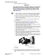
Figure 199
1.
Carriage screw (2 used)
9.
Idler spring
17.
Drive pulley
2.
Carriage screw (3 used)
10.
Pivot washer
18.
Spacer
3.
Brush plate
11.
Drive belt
19.
Flange bushing
4.
Cap screw (2 used)
12.
Idler pulley
20.
Cover
5.
Flat washer (4 used)
13.
Retaining ring
21.
Flange nut (2 used)
6.
Lock nut (6 used)
14.
Bearing
22.
Set screw (top of cover only)
7.
Idler arm
15.
Shoulder screw
8.
Idler spacer
16.
Flange head screw
Note:
Drive components for the rear roller brush are located on the opposite side
of the cutting unit from the cutting reel motor.
shows components
used when the brush drive is on the left side of the cutting unit.
Note:
The Installation Instructions for the rear roller brush kit has detailed
information regarding assembly and adjustment. Use those Instructions along
with this Service Manual when servicing the rear roller brush.
1. Position machine on a clean and level surface, lower cutting units, stop
engine, engage parking brake and remove key from the key switch.
2. Remove cover (item 20) to access rear roller brush drive components.
3. Remove roller brush drive components as necessary using
as
a guide.
Reelmaster
®
3100-D/3105-D
Page 8–43
DPA Cutting Units: Service and Repairs
20252SL Rev A
Summary of Contents for 03200 Reelmaster 3100-D
Page 4: ...NOTES NOTES Page 4 Reelmaster 3100 D 3105 D 20252SL Rev A ...
Page 6: ...g341979 Figure 1 Preface Page 6 Reelmaster 3100 D 3105 D 20252SL Rev A ...
Page 10: ...Preface Page 10 Reelmaster 3100 D 3105 D 20252SL Rev A ...
Page 20: ...Safety Safety and Instructional Decals Page 1 10 Reelmaster 3100 D 3105 D 20252SL Rev A ...
Page 44: ...Specifications and Maintenance Special Tools Page 2 24 Reelmaster 3100 D 3105 D 20252SL Rev A ...
Page 224: ...Hydraulic System Service and Repairs Page 5 148 Reelmaster 3100 D 3105 D 20252SL Rev A ...
Page 385: ......

