Controller Checks (continued)
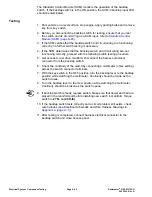
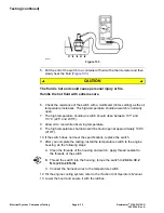
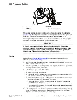
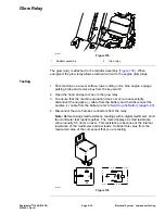
5. If any of the conditions in step 3 are not met or power to terminal 1 exists and
any of the other conditions in step 4 are not met:
A. Check the continuity of the circuitry from the battery to the glow relay and
glow plugs; refer to the Electrical Schematics in
Appendix A (page A–1)
.
B. Check the continuity of the circuitry from the battery to key switch, glow
controller, glow lamp, glow relay, and ground; refer to the Electrical
Schematics in
Appendix A (page A–1)
.
C. Replace the parts as necessary.
6. Connect the electrical connector to the fuel stop solenoid.
Electrical System: Component Testing
Page 6–42
Reelmaster
®
3100-D/3105-D
20252SL Rev A
Summary of Contents for 03200 Reelmaster 3100-D
Page 4: ...NOTES NOTES Page 4 Reelmaster 3100 D 3105 D 20252SL Rev A ...
Page 6: ...g341979 Figure 1 Preface Page 6 Reelmaster 3100 D 3105 D 20252SL Rev A ...
Page 10: ...Preface Page 10 Reelmaster 3100 D 3105 D 20252SL Rev A ...
Page 20: ...Safety Safety and Instructional Decals Page 1 10 Reelmaster 3100 D 3105 D 20252SL Rev A ...
Page 44: ...Specifications and Maintenance Special Tools Page 2 24 Reelmaster 3100 D 3105 D 20252SL Rev A ...
Page 224: ...Hydraulic System Service and Repairs Page 5 148 Reelmaster 3100 D 3105 D 20252SL Rev A ...
Page 385: ......

