
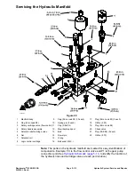
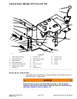

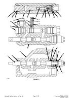


Control Valve (Model 03171)
g345779
Figure 96
1.
Control valve (2-spool)
10.
Cotter pin
19.
Carriage screw (2 each)
2.
Hydraulic fitting (straight)
11.
Valve lever
20.
O-ring
3.
90º hydraulic fitting
12.
Valve actuator trunnion
21.
O-ring
4.
Hydraulic fitting (straight)
13.
Shoulder bolt
22.
Hydraulic tube
5.
Flange nut
14.
Link (4 each)
23.
Hydraulic tube
6.
Knob
15.
Bolt
24.
Hydraulic hose
7.
90º hydraulic fitting
16.
Lock nut
25.
O-ring
8.
Valve actuator bracket
17.
Push nut
26.
Hydraulic hose
9.
Shoulder bolt
18.
Hydraulic fitting
27.
Hydraulic tube
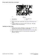
Removing the Control Valve
1. Thoroughly clean hydraulic hose ends and fittings on lift cylinder to prevent
hydraulic system contamination.
Reelmaster
®
3100-D/3105-D
Page 5–125
Hydraulic System: Service and Repairs
20252SL Rev A
Summary of Contents for 03200 Reelmaster 3100-D
Page 4: ...NOTES NOTES Page 4 Reelmaster 3100 D 3105 D 20252SL Rev A ...
Page 6: ...g341979 Figure 1 Preface Page 6 Reelmaster 3100 D 3105 D 20252SL Rev A ...
Page 10: ...Preface Page 10 Reelmaster 3100 D 3105 D 20252SL Rev A ...
Page 20: ...Safety Safety and Instructional Decals Page 1 10 Reelmaster 3100 D 3105 D 20252SL Rev A ...
Page 44: ...Specifications and Maintenance Special Tools Page 2 24 Reelmaster 3100 D 3105 D 20252SL Rev A ...
Page 224: ...Hydraulic System Service and Repairs Page 5 148 Reelmaster 3100 D 3105 D 20252SL Rev A ...
Page 385: ......