Testing (continued)
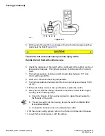
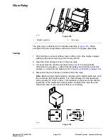
5. Check the coil resistance between terminals the 85 and 86 with a multimeter
(ohms setting). The resistance should be approximately 72 ohms (
6. Connectmultimeter (ohms setting) leads to relay terminals 30 and 87. Ground
terminal 86 and apply +12 VDC to terminal 85. The relay should make and
break continuity between terminals 30 and 87 as 12VDCis applied and
removed from terminal 85.
7. Disconnect the voltage and leads from the relay terminals.
8. Replace the relay if testing determines that the relay is damaged.
9. If the relay testing is correct and a circuit problem still exists, check the
main wire harness; refer to the Electrical Schematics and Wire Harness
Drawings/Diagrams in
Appendix A (page A–1)
.
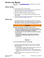
10. Connect the wire harness electrical connectors to the relay after you
complete the testing.
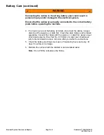
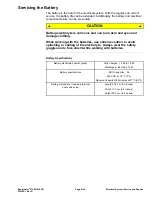
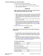
11. Connect the positive (+) cable to the battery and then connect the negative
(-) cable to the battery; refer to
Servicing the Battery (page 6–49)
.
12. Lower and secure the hood.
Electrical System: Component Testing
Page 6–36
Reelmaster
®
3100-D/3105-D
20252SL Rev A
Summary of Contents for 03200 Reelmaster 3100-D
Page 4: ...NOTES NOTES Page 4 Reelmaster 3100 D 3105 D 20252SL Rev A ...
Page 6: ...g341979 Figure 1 Preface Page 6 Reelmaster 3100 D 3105 D 20252SL Rev A ...
Page 10: ...Preface Page 10 Reelmaster 3100 D 3105 D 20252SL Rev A ...
Page 20: ...Safety Safety and Instructional Decals Page 1 10 Reelmaster 3100 D 3105 D 20252SL Rev A ...
Page 44: ...Specifications and Maintenance Special Tools Page 2 24 Reelmaster 3100 D 3105 D 20252SL Rev A ...
Page 224: ...Hydraulic System Service and Repairs Page 5 148 Reelmaster 3100 D 3105 D 20252SL Rev A ...
Page 385: ......

