Toho Electronics TRM-10C Instruction Manual Download Page 24

23


HXPRM10mnCT002E 

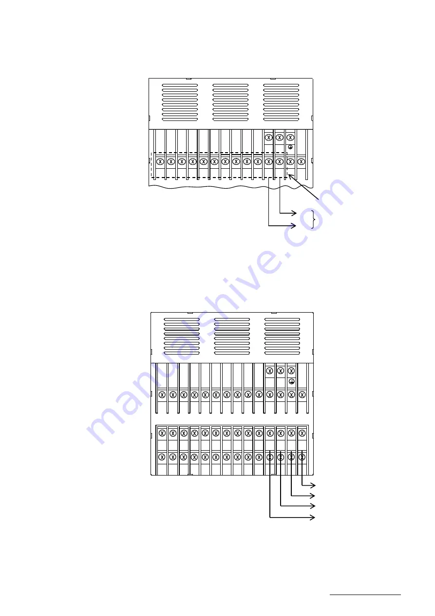
4.3.2  Alarm Output Wiring Procedure 

Wire the Alarm output refer to Fig.4.8. 


Fig. 4.8


Alarm Output Wiring 

4.3.3  DI Wiring Procedure 

Wire the DI refer to Fig.4.9. 


Fig. 4.9


 DI Wiring 

L

N

1A

1C

2A

2C

3A

3C

+

-

3-Relay output 

3C 

3A 

Relay No.3 
(Normally open) 

L

N

1C

1A

2A

3C

3A

2C

1+

B

1-

B

1

A

2+

B

2-

B

2

A

SG

RD

TD

DI

COM

DI

3

DI

2

DI

1

+

-

DI1 

DI2 

DI3 

DI.COM 

(COMMON for DI1 to DI3) 

Summary of Contents for TRM-10C

Page 1: ...TRM 10C HYBRID RECORDER PEN TYPE RECORDER INSTRUCTION MANUAL TOHO ELECTRONICS INC HXPRM10mnCT002E SEP 2016 6th Edition Copyright 2000 2016 TOHO ELECTRONICS INC All Rights Reserved...

Page 2: ...e system is expected by the error occurs due to external factors or failure the instruments take precautions to ensure the overall safety of your system 3 Take precautions to so that an alien substanc...

Page 3: ...carefully by the instrument 5 When the manual is lost or stained contact our sales representative 6 It is prohibited to copy or reproduce this manual without our permission 1 When installing this inst...

Page 4: ...autioning information in this manual Symbols used on this manual WARNING Failure to observe this information could result in death or injury Be absolutely certain to read this CAUTION Failure to obser...

Page 5: ...2 6 4 Digital Print 43 6 4 1 Manual Print 43 6 4 2 List Print 44 6 4 3 Engineering List Print 46 6 4 4 Record Start End Print 48 6 4 5 DI Manual Print option 48 6 4 6 DI Date Time Print option 48 6 4...

Page 6: ...2 When the Recorder Does not Work atAll 112 10 1 3 When There is a Big Error 113 10 1 4 When the Pen Recording Deflected 113 10 1 5 When Prints Nothing 114 10 1 6 When Printing is Faint 114 10 1 7 Whe...

Page 7: ...esentative Following accessories should be attached Chart paper Ribbon cassette Cartridge Pen Mounting bracket Instruction manual Packing Fig 1 1 Accessories Table 1 1 List of Accessories Part Name Ty...

Page 8: ...Open the chart cover to check it This instrument is shipped with the ribbon cassette back of the chart holder Chart Guide Chart Cover Note This instrument is equipped with the ribbon cassette back of...

Page 9: ...e nameplate is affixed to the middle far side of the instrument Make sure that this instrument meets your requested specification seeing the following tables Table 1 2 Type 01 1 pen type Model 02 2 pe...

Page 10: ...original nameplate is attached it may damage the door or mounting part CAUTION Storage in a poor environment may damage the appearance functions and service life of the instrument Storage Environment...

Page 11: ...10 HXPRM10mnCT002E 2 CONSTRUCTION 2 1 Appearance Fig 2 1 Appearance Cartridge pen Door Chart Holder Display keyboard Terminal block Case Mounting bracket Indication card...

Page 12: ...U V W X Y Z RUN CH No DATA Alarm Type Display Indicates an alarm type in red H is illuminated when the alarm is High And L is illuminated when the alarm is Low Neither of them is illuminated when the...

Page 13: ...t and change to the setting mode ESC key ESC function Exits that menu halfway selecting a function PRINT key PRINT function Used to perform manual print or list print key function Used to select a set...

Page 14: ...d safety of the instrument it is recommended to secure the spacing larger than the parenthesized dimensions per unit Unit mm Front Rear Side Panel Cutting 56 144 144 3 5 2 5 100 RUN ALM RUN MENU PRINT...

Page 15: ...m 2 3 WARNING Do not install the instrument in a place exposed to a combustible explosive or corrosive gas SO2 H2S etc CAUTION Install the instrument in the following places Aplace free from where hu...

Page 16: ...e IP65 Prior to mounting the instrument to the panel attach packing to the position shown in the figure The rest of the procedure is the same Fig 3 4 Mounting to the Panel in compliance with the IP65...

Page 17: ...rms to the voltage of the supply source Attach a transparent protective cover prior to turning on the POWER of the instrument Any interruption of the protective conductor inside or outside the apparat...

Page 18: ...ng conductor there may be an effect caused by noise coming from the grounding conductor It is recommended not to share it with other instrument In order to comply with the requirements of safety stand...

Page 19: ...ecommended to use a shielded input line For Pt 100 JPt 100 50m max When it is likely to be affected by induction noise particularly when wiring near the high frequency power source it is recommended t...

Page 20: ...s refer to Fig 4 3 Page 19 Fig 4 4 and Fig 4 5 Page 20 3 Put back the transparent protective cover Fig 4 4 Input Wiring mV V TC CAUTION The transparent protective cover should surely remove the left a...

Page 21: ...istor to the input terminal block of the instrument Input accuracy is effected with the shunt resistor Use the following recommended resistor Resistance 250 Rated power 1 4W Tolerance 0 1 max Temperat...

Page 22: ...ive load 0 1Aat maximum L R 7ms at maximum Inductive load Attach an anti surge protective circuit surge absorbers etc to an output terminal as required Attach a round press fitting terminal with insul...

Page 23: ...iring Example CAUTION The DI Option consists of a combination of 3 Digital inputs The alarm output consists of 3 Relay output Normally open Relay No 1 is a common output of paper empty sensor Option a...

Page 24: ...4 8 Fig 4 8 Alarm Output Wiring 4 3 3 DI Wiring Procedure Wire the DI refer to Fig 4 9 Fig 4 9 DI Wiring L N 1A 1C 2A 2C 3A 3C 3 Relay output 3C 3A Relay No 3 Normally open L N 1C 1A 2A 3C 3A 2C 1 B 1...

Page 25: ...igh frequency power source it is recommended to use a shielded twisted wire Attach a round press fitting terminal with insulated sleeve for M3 5 to the end of the electric wire Ground the shield of a...

Page 26: ...cords the right side approx 85 respectively Fig 5 2 Automatically Moving the 2 Pens and Printer CAUTION It is recommended to use our original chart paper to ensure proper recording If the chart holder...

Page 27: ...3 Moving up the Pen Push up the pen up lever to move a pen tip away from the chart paper Move up the pen Fig 5 4 Moving up the Pen CAUTION Maximum angle of the door in opened state is 135 degree Do no...

Page 28: ...to this side Fig 5 5 Taking out the Chart Holder 5 Opening the Chart Cover and Chart Guide Open the chart guide and the chart cover outwardly Fig 5 6 Opening the Chart Cover and Chart Guide Pull out t...

Page 29: ...sure to loosen the paper Fig 5 7 Loosening the Chart Paper 7 Setting the Chart Paper into the Storage Chamber Unfold the chart paper by two plies Holding the printing surface upward set it in the stor...

Page 30: ...gning the Chart Paper with Sprocket Drum Chart Holder Sectional View 9 Closing the Chart Cover and the Chart Guide Close the chart cover and the chart guide in the arrow directions Fig 5 10 Closing th...

Page 31: ...ded to feed the chart paper by 4 plies Fig 5 11 Checking Paper Feed 11 Putting Back the Chart Holder Push in the chart holder horizontally into the case until it is locked Fig 5 12 Putting Back the Ch...

Page 32: ...ressing the FEED key to Check Paper Feed Press the FEED key on the display keyboard to feed the chart paper Fig 5 13 Pressing the FEED key 14 Pressing the RUN key to Restart Operation UN CH No DATA Th...

Page 33: ...ock the door Pull the door to this side to open it See Fig 5 3 on Page 26 3 Detaching the Cartridge Pen Pull out the cartridge pen to this side Fig 5 14 Detaching the Cartridge Pen Note When pulling o...

Page 34: ...aching the Cartridge Pen Reattach the cartridge pen to the pen holder Push it in firmly until it clicks Fig 5 16 Reattaching the Cartridge Pen 6 Pressing the RUN Key to Restart Operation Pen Cap Pen H...

Page 35: ...up the pen see Fig 5 4 on Page 26 4 Taking out the Chart Holder Put your fingers onto the levers at both sides of the chart holder and pull it out to this side See Fig 5 5 on Page 27 The guide shaft p...

Page 36: ...9 Detaching from the Main Shaft Viewing from the right side section the hook of the ribbon cassette has been engaged with the main shaft Fig 5 20 Ribbon Cassette Sectional View Ribbon Guide Shaft Lowe...

Page 37: ...te Pull out the ribbon cassette horizontally If the gear of the ribbon cassette touches the printer move the printer further to the right 9 Unslacking the Ink Ribbon Set the new ink ribbon Turn the ge...

Page 38: ...n shaft in such a manner that the hook of the ribbon cassette will be engaged with the main shaft Fig 5 24 Reattaching to the Main Shaft Ribbon Cassette Sectional View Main Shaft Guide Shaft Ribbon Ca...

Page 39: ...ing to the Guide Shaft 13 Putting back the Chart Holder Put back the chart holder horizontally into the case until it is locked See Fig 5 12 on Page 30 14 Moving down the Pen to Close the Door Use the...

Page 40: ...ay Screen at Power on Note When electric power failure occurs the initialization is performed after power recovery And it becomes the above initial state The printout data are eliminated in initializa...

Page 41: ...g Colors Channel No Color Red Green 6 2 2 Printing Color Various digital prints are recorded in purple 6 2 3 Pen Gap Fig 6 2 shows the gap between No 1 and No 2 pens Fig 6 2 Gap between Pens 6 2 4 Gap...

Page 42: ...Recording Operation To start stop recording press the RUN key To stop hold down the RUN key for 3 seconds or more RUN lamp is unilluminated when stop recording 6 3 2 Feed the Chart Paper The chart pa...

Page 43: ...ge Priority in Reference Note Logging print will not be the wait printing state At the start time of Logging print if the prior Logging print is printing the next one cannot print Prolong the printing...

Page 44: ...t Note Analog recording is continued while manual print is running Chart paper is fed forcibly If an alarm is activated while manual print is running alarm print will be performed when manual print en...

Page 45: ...ling value engineering unit Setting alarm type Comment Others 1 List print operating procedure Press the PRINT key Use the PRINT key to display and press the ENT key Use the PRINT key to select Pressi...

Page 46: ...AG01 NORMAL 0 0 50 0 CH2 mA SCALE 4 00 20 00mA 0 00 100 00 CH LV ALM RLY 1 1 H 28 0 1 1 2 L 18 0 2 4 H 30 00 3 CH DIGITAL ZONE mm 1 ON 0 50 2 OFF 50 100 CH PARTIAL 2 50 40 00 COMMENT 2 TRM PEN 3 12345...

Page 47: ...he PRINT key to select Pressing the ENT key executes engineering list print Once engineering list print starts the display is automatically returned to the Data Display screen Upon termination of engi...

Page 48: ...00 2 EXT 805 ON 0 0 0 8000 COM_ADR 01 SPEED 9600BPS DATA 8bit PARITY NONE STOP 1bit DI 1 COMMENT1 2 MAN_PRINT 3 TIMEPRINT Alarm Print Set Value ON 1 occurrence recovery Logging Print Set value ON OFF...

Page 49: ...l Print option DI manual print prints measurements and time on paper by turning on DI The content of the print is the same as 6 4 1 Manual Print 1 DI function of the engineering mode is set Please ref...

Page 50: ...to the setup mode 1 DI function of the engineering mode is set Please refer to 7 2 9 DI function for details Date Time print is synchronous print Date Time print is asynchronous print 2 DI is operate...

Page 51: ...rvals of 2 4 seconds Data renewal period 120ms 6 5 2 Manual Display Indicates the Process variable of specific channel it updates every measurement cycle 120ms The data is the same as Auto display Pre...

Page 52: ...turn from the setup mode to the recording mode user mode press the MENU key for 3 seconds or more again The following describes how to set the following items The following shows a display map of the...

Page 53: ...rding Partial compression expansion Digital print Tag Comment words Setting the password Zone Recording Partial Compression Expansion Digital Print Tag Comment Words Setting Mode Setting Copy from Cha...

Page 54: ...rm OFF relay OFF Engineering unit all channels BF 43 00 Chart speed 20mm h 20mm h Time 2000 01 01 00 00 Sets up the present time Japan standard time GMT 09 00 Zone setting all channels 0 100 Partial c...

Page 55: ...difference average mode to Unnecessary channels can be skipped mode Setting Channel Mode Key Current Voltage Input Key Thermocouple Input Resistance temperature detector Input Scaling Square Root Deca...

Page 56: ...n and numeral Use the key to shift a digit Press the ENT key Use the key to select a sign and numeral Use the key to shift a digit Press the ENT key Press the ENT key Setting is completed To return to...

Page 57: ...56 HXPRM10mnCT002E Note In the or mode press the ENT key to select the range Use the key you can select the type out of the range ENT Key mV mV mV mV Range Mode...

Page 58: ...the key to select a range 50 mV Press the ENT key Use the key to select a numeral Use the key to shift a digit Press the ENT key Use the key to select a numeral Use the key to shift a digit Press the...

Page 59: ...T key Use the key to select a numeral Use the key to shift a digit Press the ENT key Press the ENT key Setting is completed To return to the user mode hold down the MENU key for 3 seconds or more FEED...

Page 60: ...a numeral Use the key to shift a digit Press the ENT key Use the key to select a numeral Use the key to shift a digit Press the key again in the lowest digit right end to blink a decimal point Use the...

Page 61: ...le L SCALR Scaling upper limit value Scale R IN Input voltage OUT Output Scaling value When an input value is 1 or more 1 to 100 OUT SCALR SCALL SCALL When an input value is less than 1 OUT IN SPAN L...

Page 62: ...e the key to shift a digit Press the ENT key Use the key to select a numeral Use the key to shift a digit Press the ENT key Use the key to select a numeral Use the key to shift a digit Press the ENT k...

Page 63: ...ides by the following relational expression OUT1 IN OUT 10 OUT1 LGSCALL Log10 SCALL LGSCALR Log10 SCALR Example When makes setting in previous page the display is as follow table Input voltage V Displ...

Page 64: ...s the ENT key Setting is completed To return to the user mode hold down the MENU key for 3 seconds or more About Difference Sum and Average The channel to be set must be larger than the one on which c...

Page 65: ...leted To return to the user mode hold down the MENU key for 3 seconds or more Note Setting all the channels to Skip indicates an error At least one channel should be set to measurement The skip channe...

Page 66: ...arm set value of 2 000 and alarm output relay No 1 Hold down the MENU key for 3 seconds or more to enter the setup mode Use the key to indicate Press the ENT key Use the key to select the channel you...

Page 67: ...ress the ENT key If the alarm output is set to ON set the relay number Use the key to select the relay number out of 1 to 3 and press the ENT key Press the ENT key Setting is completed When you want t...

Page 68: ...character in the same manner When the number of unit characters is less than 6 enter a code to end Press the ENT key Press the ENT key Setting is completed To return to the user mode hold down the ME...

Page 69: ...68 HXPRM10mnCT002E 1 Character Code Table Example The code number for C is 43...

Page 70: ...more to enter the setup mode Use the key to indicate and press the ENT key Use the key to select the 1st chart speed and press the ENT key Use the key to set the 1st chart speed and press the ENT key...

Page 71: ...chart speed Restriction of printing by chart speed When the chart speed is 0 h it s printed with forcible chart feed When the chart speed is more than 120 h not printing as shown the Table above List...

Page 72: ...nter the setup mode Use the key to indicate and press the ENT key Use the key to select the copy from channel Use the key to select the copy to channel and press the ENT key Press the ENT key To retur...

Page 73: ...ther the measured data for each channel is to be printed or not Tag Set the tag which is to be printed instead of a channel number for logging print or manual print Setting up to 5 characters See Page...

Page 74: ...nting position in percentage Use the key to select a numeral and use the key to shift a digit Press the ENT key Set a span printing position in percentage Operate in the same manner as setting the zer...

Page 75: ...the ENT key Set a boundary point position in percentage Use the key to select a numeral and use the key to shift a digit Press the ENT key Set a boundary point position to 0500 0 Use the key to select...

Page 76: ...icate and press the ENT key Use the key to select the channel you want to set and press the ENT key Use the key to switch from to and press the ENT key Press the ENT key Setting is completed To return...

Page 77: ...ift a digit Press the ENT key Set the 2nd character to end in the same manner Set as the 3rd character to end and press the ENT key Press the ENT key Setting is completed To return to the user mode ho...

Page 78: ...manner as setting the 1st character to end Repeat setting for each channel Press the ENT key Setting is completed To return to the user mode hold down the MENU key for 3 seconds or more ENT MENU ESC 3...

Page 79: ...g Press the ENT key After reset enter the engineering mode The following describes how to set the following items The following shows a display map of the Enginneering mode Use the key to operate 7 2...

Page 80: ...Comment 3 print Asynchronous Manual print Asynchronous Date and time print Asynchronous Setting DI No Function Setting Recording start stop INT EXT selection Tag channel print selection Alarm print O...

Page 81: ...e Logging Print Sync ASync Print gap correction Record Start End print INT Ch OFF ON 6H 00 00 Sync print OFF OFF Use the RUN key COM communication Protocol Address Baud rate Data length Parity bit Sto...

Page 82: ...ey to indicate and press the ENT key 7 2 2 Burnout ON OFF Setting Burnout High to deflect the recording over the span for each channel is possible Example When setting Burnout High for Channel 2 Enter...

Page 83: ...e ENT key 7 2 4 Reference Junction Compensation The following describes how to set the method for compensating an electromotive force generated between a thermocouple wire or compensation lead wire an...

Page 84: ...value or the key to shift a digit Once the numerical value is decided press the ENT key Setting is completed Returned to the channel setting Example When Channel 1 input compensates Channel 2 referenc...

Page 85: ...Sets a recording start stop trigger select tag channel print or set alarm print and logging print 1 Recording start stop trigger setting Set whether the trigger of recording start stop should be by th...

Page 86: ...n 3 Alarm print ON OFF Setting the alarm print ON OFF When ON1 prints the alarm occurring and the alarm recovering When ON2 prints only the alarm occurring Example When sets both the alarm occurring a...

Page 87: ...to select and press the ENT key Use the key to display and press the ENT key Use the key to alter a numeral and key to shift a digit Then set the time and press the ENT key Use the key to display and...

Page 88: ...ed to the print gap correction Setting screen 6 Record Start End Print OFF SYNC ASYNC Set Record Start End print to OFF Synchronous print Asynchronous print Example When setting Record Start End print...

Page 89: ...o indicate and press the ENT key Select from Use the key to indicate and press the ENT key Select from 1200 2400 4800 9600 19200 38400 Use the key to indicate and press the ENT key Select from 7 bit 8...

Page 90: ...ey to indicate and press the ENT key Use the key to select and press the ENT key Use the key to indicate and press the ENT key Setting is completed Returned to the DI3 Function Setting screen ENT PRIN...

Page 91: ...point of 1 channel pen recording Enter the engineering mode See the key operation in page 78 Use the key to indicate and press the ENT key Use the key to select and press the ENT key Use the key to se...

Page 92: ...T key Display indicates the set counter value Setting is completed Returned to the Span Point Calibration screen 7 2 12 Data Calibration Calibrate the voltage resistance temperature detector and refer...

Page 93: ...ess the ENT key Enter 35 mV After 10 seconds make sure that the ALM lamp unilluminated and press the ENT key Enter 55 mV After 10 seconds make sure that the ALM lamp unilluminated and press the ENT ke...

Page 94: ...h the key and if incorrect select respectively Then press the ENT key Display Operation Keys Description ENT ENT PRINT PRINT ENT ENT PRINT ENT ENT ENT ENT PRINT Note During calibration ALM lamp indica...

Page 95: ...on in page 99 If the calibration is correct select with the key and if incorrect select respectively Then press the ENT key 7 3 Terminating the Engineering Mode Example The following describes how to...

Page 96: ...peed etc Controlling of the recorder Partially Selection to print recording start stop and changing display etc For the functions to see the separate Communication Command Reference Manual charged 8 1...

Page 97: ...nsmitting function does not reply The data format error status can be confirmed by the ESC S command described later 4 Control codes ESC 1B HEX hexadecimal This code is used for an escape sequence suc...

Page 98: ...command is received the recorder transfers the process variable data to the transmit buffer when the ESC T command is received 2 Updating the Data ESC Once this command is received the recorder transf...

Page 99: ...ata S Skip All the data are spaces Data information 2 1 byte E Final data Space Other data to Alarm information 1 byte each 4 bytes in total H Upper limit alarm L Lower limit alarm Space Alarm OFF or...

Page 100: ...EVEL3L LEVEL H Upper limit alarm bit at the alarm level x LEVEL L Lower limit alarm bit at the alarm level x S Process variable data to 2 byte hexadecimal data The higher and lower bytes can be revers...

Page 101: ...nel to Output end channel to When the number of channels is one specify S_CH E_CH Example LF 01 02 CR LF The unit and decimal point of 01 to 02 channel output 4 Data Format Data information 1 1 byte N...

Page 102: ...nd Receiving this command outputs the status for the command received so far 2 Status Output Table 8 1 Status output list Status factor Status output Status factor A D END Syntax error Paper empty The...

Page 103: ...esignation BO BINARY Mode only Close Command Open the Link Prepares For the Process Variable Data Output Prepares the Update Data Sends the Update Data Determines the Process Variable Data Output Orde...

Page 104: ...tinent function code if an error occurs during command transmission an error response is returned in the fixed format described in this section Example of slave response function code 06H command erro...

Page 105: ...s Component Data length Data Slave address 1 Function code 1 04H Data Relative start address high order 1 00H Relative start address low order 1 32H Read data count high order 1 00H Read data count lo...

Page 106: ...version 6 16 6 30015 E Software version 7 16 7 30016 F Software version 8 16 8 30017 10 Software version 9 16 9 30018 11 Software version 10 16 10 30019 12 Software version 11 16 11 30020 13 Software...

Page 107: ...printing 30062 3D Reserve 30100 63 Reserve 30101 64 Channel status CH01 00bit Alarm 1 1 ON 0 OFF 01bit Alarm 2 1 ON 0 OFF 02bit Alarm 3 1 ON 0 OFF 03bit Alarm 4 1 ON 0 OFF 30102 65 CH02 30103 66 Rese...

Page 108: ...9 Unit 4 4 30139 8A Reserve 8 3 5 Reading from or Writing to the Holding Register Area The holding register area is a read write area Parameter settings and the start and stop command of the recording...

Page 109: ...en recording deflected Are recording indication done properly Any big error in indicated values or pen recording position Any improper pen recording Any blurred pen recording or printout Proper printo...

Page 110: ...he reference With the apparatus left in the working conditions make adjustment according to the instructions in 7 2 11 Point calibration See Page 90 9 5 Calibration Data Calibration Calibrate a proces...

Page 111: ...Detector Conduct calibration according to the instructions in 7 2 12 Data Calibration Calibration of the resistance temperature detector See Page 93 Precision Dial Resistor TRM 10C Recorder Input Ter...

Page 112: ...part for the difference with true value 0 5 as the right RJC temperature 24 5 0 5 25 0 Conduct calibration according to the instructions in 7 2 12 Data Calibration Calibration of reference junction co...

Page 113: ...ment or our sales representative Remedy Trouble Does not work at all Big error Recording error Pen recording deflected Nothing is printed at all Faint printing Chart paper feed error Chart paper is no...

Page 114: ...to 111 Set properly See 7 1 1 Scaling on Page 54 Pen recording position of Zero Span properly Calibrate again See 7 2 11 on Page 90 Recording error Flow chart 3 Pen recording deflected 0 or 100 Input...

Page 115: ...instrument or our sales representative Take remedy according to 10 2 on Page 116 Select the RUN mode See 2 2 2 on Page 12 2 2 1 Set properly See 5 3 on Page 34 Ribbon fed properly Replace the ribbon...

Page 116: ...er fed by FEED key DI contact for remote operation OFF Change Chart speed Turn on the DI contact See 7 2 9 on Page 89 Flow chart 7 Chart paper feed improper Chart cover locked properly Chart paper set...

Page 117: ...ading error Engineering data EEP READ3 Non volatile memory Reading error ADC Calibration data RJC ERROR The measurement of the RJC internal temperature sensor is abnormal Operation error Calibration e...

Page 118: ...multiple errors are encountered their error numbers are displayed with automatic scrolling When an error restores an error display can be reset to the input of RUN key CAUTION While indicates an erro...

Page 119: ...t Allowable signal source resistance 10k max in mV TC input without burnout 100 max in mV TC input with burnout 1k max in Voltage input 10 max per line in Resistance temperature detector input Normal...

Page 120: ...onsumption 100V Max power consumption 1 pen About 20VA About 30VA 2 pen About 25VA About 35VA 11 1 5 Normal Operating Conditions Ambient temperature 0 to 50 Ambient humidity 20 to 80 RH Supply voltage...

Page 121: ...5 Setting accuracy Setting accuracy 11 1 7Low Voltage Directive and EMC Directive Low Voltage Directive EN61010 1 EMC Directive EN61326 1 Class A At the EN61000 4 3 test condition DC voltage DC curre...

Page 122: ...1 K E J T C N PL U L 0 5 Table 11 2 Measurement Range Type RANGE Measurement range Measurement Digital Analog Accuracy Max resolution Accuracy DC voltage DC contact Input 10 to 10mV 0 2 of rdg 3digit...

Page 123: ...0 15 of rdg 1 328 0 to 1112 0 F 0 15 of rdg 0 7 F 328 to 148 F 0 15 of rdg 1 8 F K3 200 0 to 300 0 0 15 of rdg 0 3 200 to 100 0 15 of rdg 1 328 0 to 572 0 F 0 15 of rdg 0 5 F 328 to 148 F 0 15 of rdg...

Page 124: ...to 572 F 67 7 F 572 to 1472 F 33 8 F PL 0 0 to 1390 0 0 15 of rdg 0 7 32 0 to 2534 0 F 0 15 of rdg 1 3 F U 200 0 to 400 0 0 15 of rdg 0 5 200 to 100 0 15 of rdg 0 7 328 0 to 752 0 F 0 15 of rdg 0 9 F...

Page 125: ...igits Analog recording accuracy 4 1000 1000 10 digits 0 01V Example 2 When Type K is 0 0 200 0 and Scaling is 0 00 200 00 Range accuracy rating 0 15 200 0 0 3 Input 200 0 6 6 digits Scaling factor 10...

Page 126: ...play value Normally the accuracy rating is less than 1 digit and you cannot read by significant digit 4 Difference Sum and Average The accuracy rating of Difference Sum and Average is as following for...

Page 127: ...Wire dot one color ink ribbon Recording Width 100 Step Response Time 1 0 s max 95 response to IEC 1143 Chart Paper Length 16m Width 114 Folding width 40 The length of the Clean Chart is 12 m Chart Sp...

Page 128: ...t Alarm function Logging print ON OFF Reference time Interval Logging print Sync ASync Print gap correction ON OFF Alarm hysteresis Burn out DI function Option Manual print Prints Measurement result b...

Page 129: ...t Alarm Print Prints Occurrence time Occurrence channel Setting No and Alarm type in purple at occurring an alarm Alarm Recovery Print Prints Recovery time Recovery channel Setting No and Alarm type i...

Reviews: