UM-17
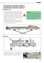
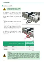
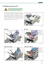
Cobot Transfer Unit
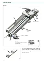
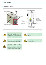
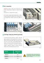
Air connection
Fig. 23
Fig. 24
Fig. 22
E
E
FF
AA
DD
BB
CC
(
A-B-C-D
) Air inlets to power robot accessories (fig. 23
and 24). Corresponding air outlets are on the axis carriage
(fig.22).
The cable carrier is supplied with 4 air cables.
(
E-F
) Air inlet for carriage clamping elements (fig. 24. Clamp-
ing elements optional if requested on order, see below chap-
ter). Corresponding air outlets are on the axis carriage (fig.
22).
Carriage clamping element (optional)
Fig. 25
If requested during the order phase, the axis comes with
clamping elements on the carriage that work on linear rails.
With this option, the carriage presents open sides like the
one shown in Fig.23. These are pneumatically activated el-
ements. Pressurized air holds the clamping element open.
The absence of pressurized air closes them and blocks the
carriage. To unblock the carriage, it is necessary to restore
pressure to the circuit. Working pressure: 5.5 bar.
Axis type
Clamping force
[N]
CTU130-1I
800
CTU160-1I
1200
CTU220-1I
1500
Tab. 6
Clamping force refers to both clamps actu-
ated via E and F connections, do not activate
only one connection.
E
E FF
AA
DD
BB
CC
Summary of Contents for ROLLON CTU 220-1I
Page 2: ......
Page 44: ...UM 42 Notes Notes...
Page 45: ...UM 43 Cobot Transfer Unit Notes...
Page 46: ...UM 44 Notes Notes...
Page 47: ......

